122 Diagnosis procedure
9.2)
Static load
The repair procedure includes static load tests.
If this is not feasible, the same tests can be run with the TIG
welding technique, but this is more difficult.
IMPORTANT!: with static load, in order to avoid
damage, disconnect the H.F. generation circuit follo-
wing the directions given in chapter 8 (Warnings,
precautions ).
IMPORTANT!: on static load, in order to prevent
tripping either the arc-force function, overheating
protection, or saturation at generator output, load
value must be adapted according to the supplied
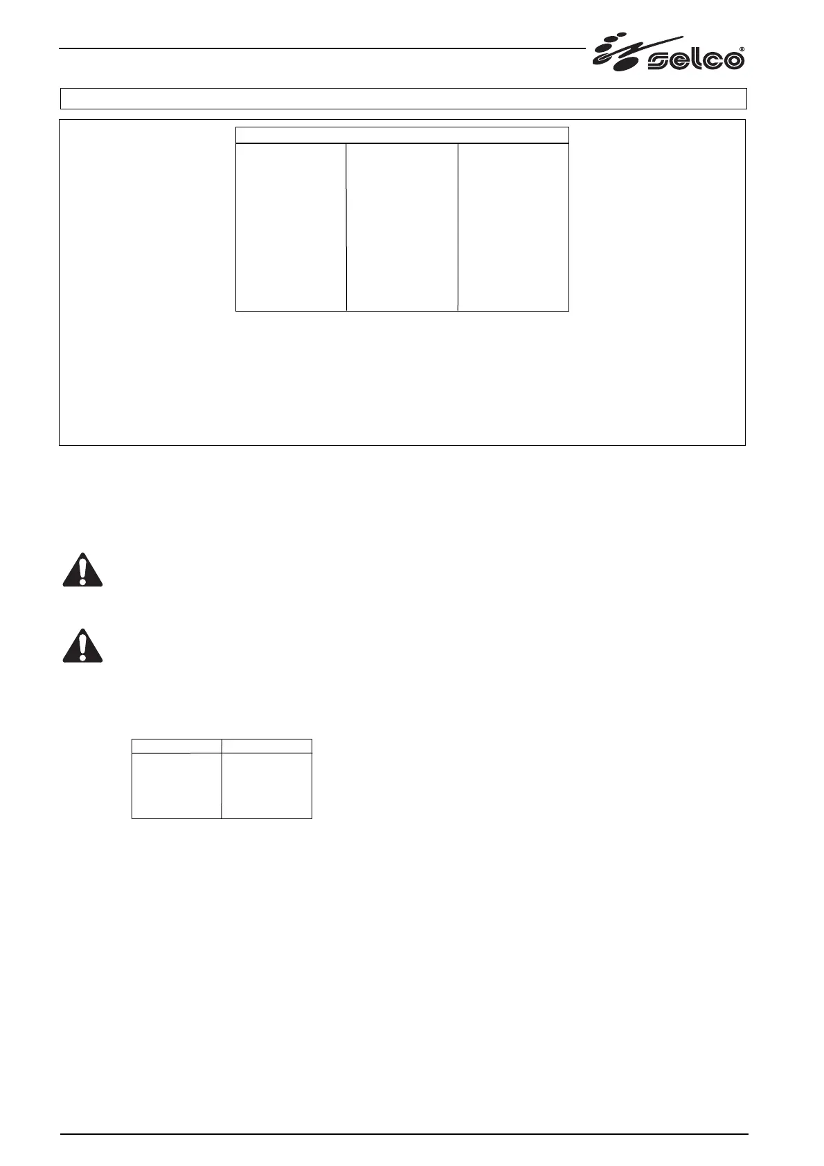
current. For G 240 and G 240 TLH, with reference
to the SELCO normalised loads (see TAB. 03), loads 3, 4, 5, 6
and 8 are required selected, depending on current, accor-
ding to the following diagram:
9.3)
Repair tools
- full set of fork wrenches
- full set of pipe wrenches for hexagon nuts
- full set of screwdrivers for single-slot screws
- full set of screwdrivers for cross-slot screws
- complete set of Allen keys
- a torque cross-slotted screwdriver for M3 screws
with facility for setting tightness torque in the range
1 to 2 Nxm 0.1 with precision of 0.1 Nxm.
- a pair of crimping pliers for insulated terminals
(blue, red and yellow)
- a pair of pliers for AMP contacts.
- a pair of pincers and nippers suitable for electronic
components.
- a bigger pair of nippers for cutting small gauge steel
sheet.
- a pair of pincers suitable for tightening the gas pipe
end rings.
- a soldering iron for electronic components with
minimum capacity of 50 W.
- an unwelding station - off-the shelf unwelding
tracce may be used instead.
10) DIAGNOSIS PROCEDURE .
10.1)
General information
The diagnosis procedure is according to this logic: starting off
from a known situation, you are asked to perform a set of
successive operations, while checking that the machine
responds correctly at each stage.
10.2)
Agreements
Unless otherwise specified, when you are requested to take a
measurement between a pair of terminals - e.g. a-aa - this
means that the red prod (or the oscilloscope probe) is placed on
the left-hand terminal (on a in this example), while the black
prod (or the ground cable of the oscilloscope) is positioned on
the right-hand one (on aa in this example).
The pins of the connector are identified by the name of the con-
nector itself followed by a slash character and by the number of
the pin; e.g. CN 1/2 identifies the pin 2 of the connector CN1.
In the remaining part of this chapter, when you are asked to
measure a signal present on any one connector on board
15.14.254, it means that the probe tips must be applied to the
welding side of the board (i.e. the accessible external part).
TAB. 03
Load n.
1)
2)
3)
4)
5)
6)
7)
8)
9)
10)
Resistance (Ohm)
8.8
8.8
4.4
1.76
0.88
0.44
0.44
0.22
0.22
0.15
Power (KW)
0.22
0.22
0.44
1.1
2.2
4.4
4.4
8.8
8.8
13.1
SELCO normalised loads
Current (A)
5
50
120
240
Load n.
3
8
3+8
4+5+6+8
NOTE : When designing an electrical panel containing loads for
testing welding equipments, there must be a facility for inputting
several loads (as listed in the table) in parallel by means of
switches.
In the remainder of this manual, we shall use the symbol + for
inputting two loads in parallel (e.g. 3 + 8 means inputting
normalised loads 3 and 8 in parallel).







 To Next Page