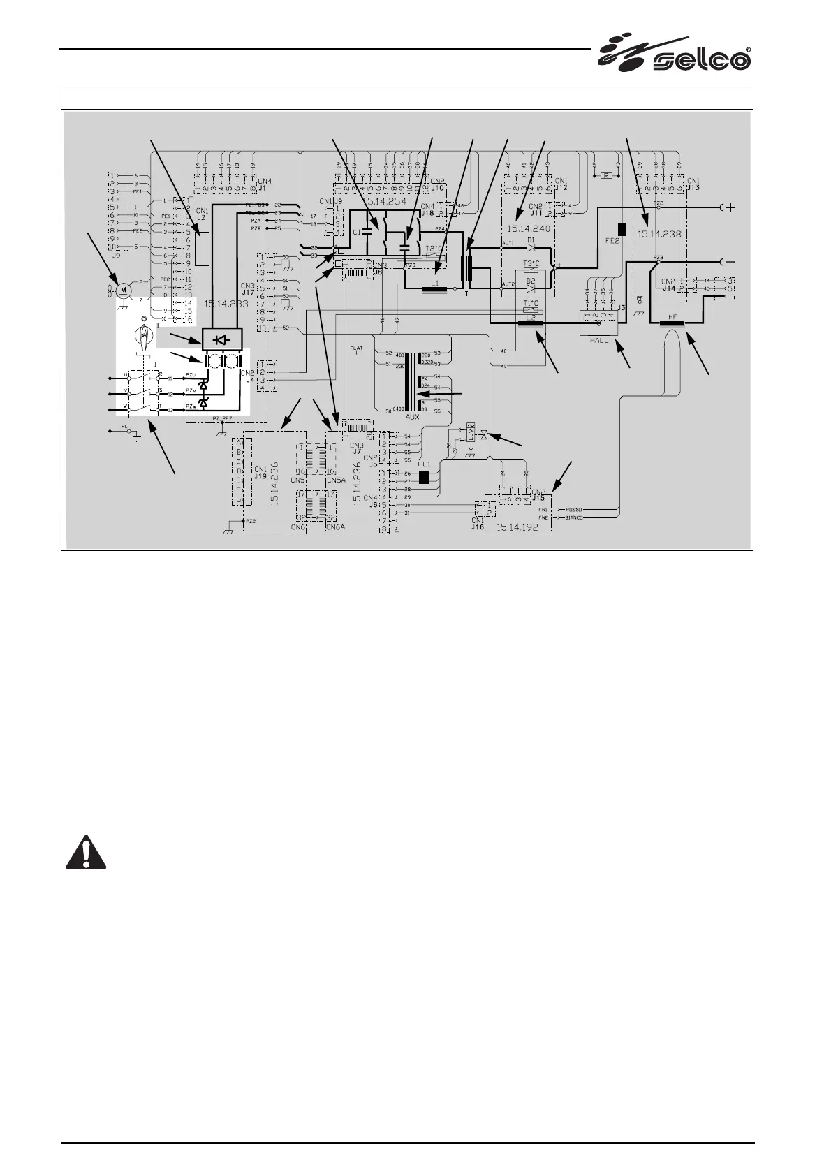
88 Description of machine operation
5) DESCRIPTION OF MACHINE OPERATION.
The power undergoes initial AC/DC conversion by the input
rectifier bridge (c) , subsequent AC/DC conversion at high fre-
quency by the inverter (d) , transfer via the insulation transfor-
mer (f) to the output circuits and final AC/DC conversion by the
output rectifier (g) .
More details:
5.1)
Master switch (a) - input filter for suppressing radio noise
and protecting against power line over-voltage (b) .
(see fig. 3-4)
The three power supply cables are cut off by means of the
switch a). The yellow-green cable is fixed to the terminal mar-
ked by the earth symbol and located on the intermediate metal
support.
IMPORTANT !: When accessing parts inside the
machine, remember that turning off the switch will
not prevent the danger of electric shocks. We the-
refore advise you to remove the power plug.
When the switch is closed, the input voltage is applied to the
board 15.14.233 containing the line overvoltage suppressor cir-
cuit (b), consisting of three varistor (see note), and the radio
interference suppressor circuit (b) (see note) connected to earth
via a screw and metal column.
NOTE : If the electrical component know as a varistor is placed
between the two power supply phases, when an instantaneous
voltage in excess of 460 V appears on its terminals, the varistor
very rapidly becomes conductive, absorbing a current peak
which is sufficient to limit the said over-voltage and it thus pro-
tects the other parts of the machine.
This process has no destructive effect on the component if the
energy generated by the voltage peak is low, as in the case of
atmospheric lightning strikes. If, however, over-voltage is high
and prolonged, the varistor cannot dissipate this high energy
and blows.
This happens if, for example, the machine is wrongly connected
to 460 Vac mains voltage, or following over-voltage caused by
non stabilised power units of inadequate capacity.
FIG. 3





 To Next Page