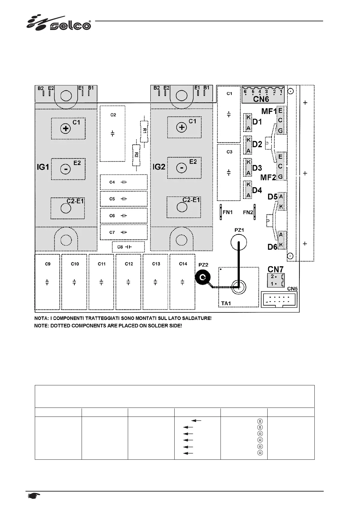
10.3) Power inverter PC board 15.14.176
This board performs the following functions:
- power inverter
Power IGBT module (IG1 & IG2) replacing instructions:
- MOUNTING & TERMINALS: use torque screw driver @ 3 Nxm (26 lbxin)
- use thermal grease as necessary.
Anyway, in case of inverter failure use of replacement kit 14.60.069 is suggested (see also "PC Boards location" section
above).
NOTE: Values below are referred to each sigle component tested alone (without any connection); any other other value
in this page is referred to normal conditions (with all connections correctly made).
Unless specified otherwise, all the measurements must be taken with the boards fitted, together with their connections!
32 Description, testing and replacement of the electronic boards, current calibration
MODULO IGBT - IG1/IG2 C2-E1 C1
E2 C2-E1
B1 C2-E1
B1 C1
B2 E2
B2 C2-E1
+0.4Vdc
+0.4Vdc
∞ Ω
∞ Ω
∞ Ω
∞ Ω
Functional part Generator/Mode Component Test point Value Notes