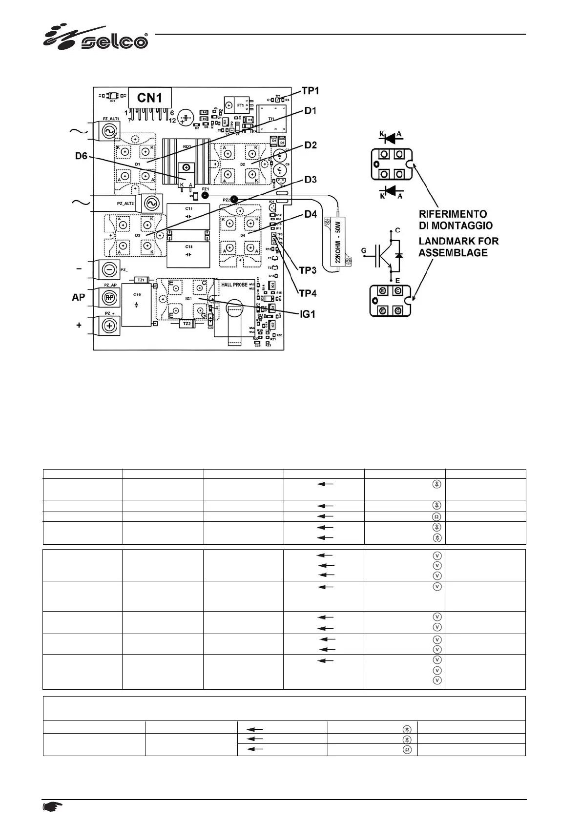
10.7) Secondary rectifier and pilot arc PC board 15.14.277
Power diodes module and IGBT replacing instructions :
- MOUNTING COMPONENTS ON HEATSINK: use torque screw driver @ 1.7 Nxm (15 lbxin)
- PC BOARD MOUNTING: use torque screw driver @ 1.5 Nxm (13 lbxin)
- use thermal grease as necessary.
In the event of a failure of the secondary we recommend that you use:
Complete spare kit 14.60.065 (see also previous section "PC BOARDS’ LOCATION" )
or
spare kit 15.18.029, including board 15.14.277 + IGBT pilot arc (see also spare parts' list in section 11).
NOTE: Values below are referred to each sigle component tested alone (without any connection); any other other value
in this page is referred to normal conditions (with all connections correctly made).
Unless specified otherwise, all the measurements must be taken with the boards fitted, together with their connections!
38 Description, testing and replacement of the electronic boards, current calibration
Power supplies
Secondary
rectifier
Pilot arc control
Output pilot arc
Hall effect probe
cutting current
ON
ON
ON
ON
ON
-
D1...D4
-
IG1
HALL PROBE
CN1/6 CN1/12
TP4 AP
TP3 AP
+ -
(open circuit
voltage)
CN1/7 CN1/1
CN1/7 CN1/1
AP -
AP -
TP1 AP
+24Vdc
+15Vdc
-15Vdc
+250Vdc
± 15%
0Vdc
1.2Vdc
0Vdc
+120Vdc
+8Vdc
+8Vdc
0Vdc
PT push
OFF pilot
ON pilot
OFF pilot
ON pilot
PT released
Pilot arc
Cutting arc
Functional part
Secondary
rectifier
Clamp diode
Clamp resistor
Pilot arc IGBT
Generator / Mode
OFF
OFF
OFF
OFF
Component
D1...D4
D6
R1
IG1
Test point
A K
A K
PZ2 PZ1
E C
E G
Value
+0.3Vdc
+0.4Vdc
22kΩ
+0.4Vdc
+0.3Vdc
Notes
DIODE
IGBT
D1...D4
IG1
A K
E C
E G
+0.4Vdc
+0.4Vdc
∞





 To Next Page