Unless specified otherwise, all the measurements must be taken with the boards fitted, together with their connections!
Description, testing and replacement of the electronic boards, current calibration 35
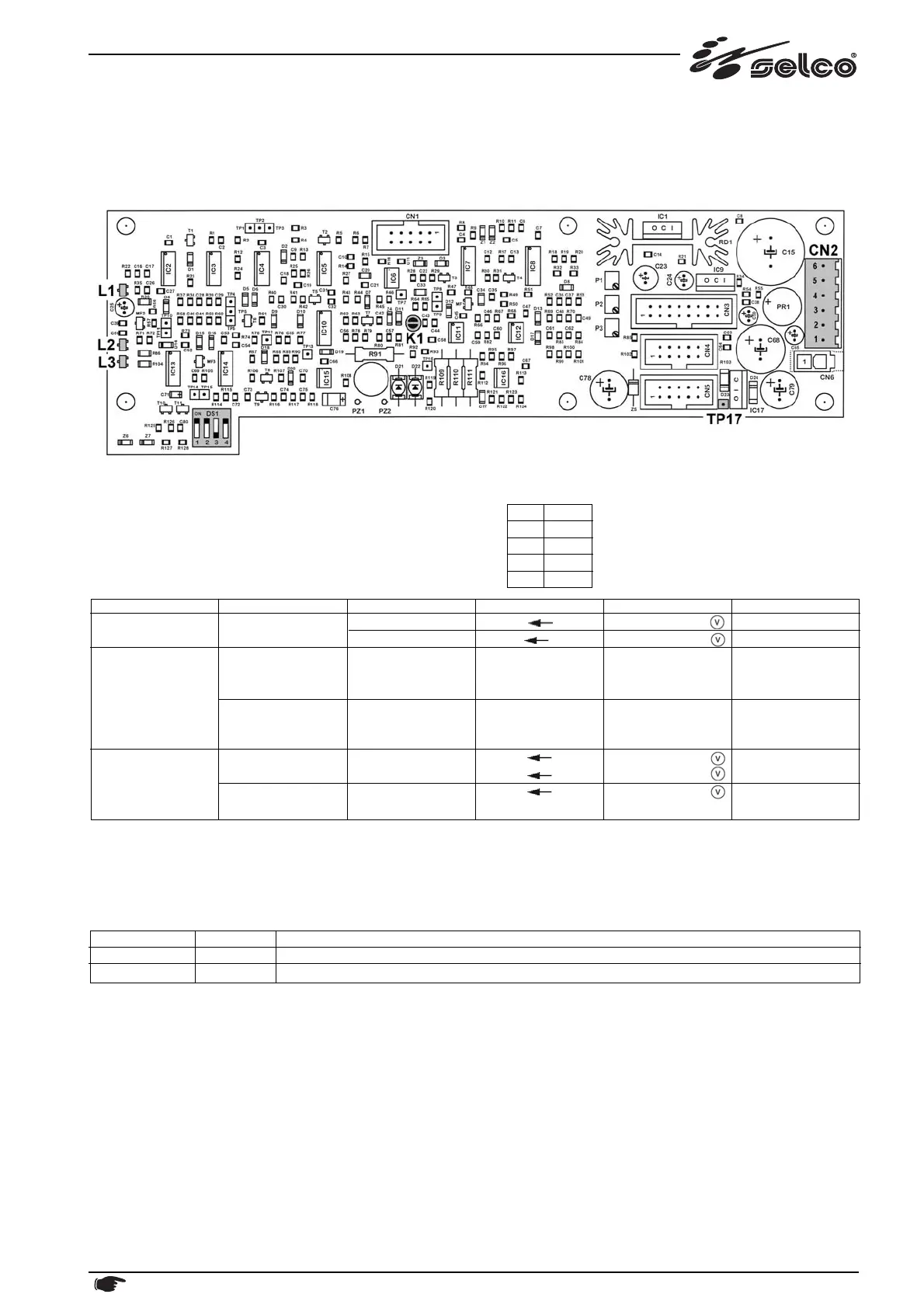
10.4) Resonant inverter control PC board 15.14.152
This board performs the following functions:
- resonant inverter control logic
- welding current reading
Soldered jumpers (factory setted): Dip-switch (factory setted):
K1 = OPEN DS1 G90
1ON
2ON
3 OFF
4ON
Notes:
L1 = Inverter Disabled (no power out), due to "POT" signal or internal aux. power supply voltage low or primary overcurrent
L2 = Inverter Enabled (power out)
L3 = "POT" signal, that is Inverter Disabled due to microprocessor logic command, coming from Front Panel PC Board.
* Note: fuses are located on Aux. Power Supply PC board 15.14.271 (see related section above).
Functional part
Aux. power supplies
Inverter control
Output current
(hall effect probe)
Generator/Mode
ON
ON
ON
ON
ON
Componente
-
-
L1
L2
L3
L1
L2
L3
-
-
-
Test point
CN2/6 CN2/3
TP17 CN2/3
-
-
-
-
-
-
CN2/4 CN2/3
CN2/1 CN2/3
CN2/2 CN2/3
Valore
+26Vdc
-10Vdc
ON
OFF
ON
OFF
ON
OFF
+15Vdc
-15Vdc
+2.20Vdc
+0.55Vdc
Note
V6
V8a
PT released
PT released
PT released
PT push
PT push
PT push
V6a
V8b
Cutting arc
Pilot arc
Related circuit
Inverter control logic, Hall probe, thermal alarm
Main positive supply (welding & inverter control logic, Hall probe).
Power supply
V6a
V8a, V8b
Fuse*
F9
F7
 Loading...