Unless specified otherwise, all the measurements must be taken with the boards fitted, together with their connections!
CHECKING THE INVERTER AND SECONDARY RECTIFIER OPERATION
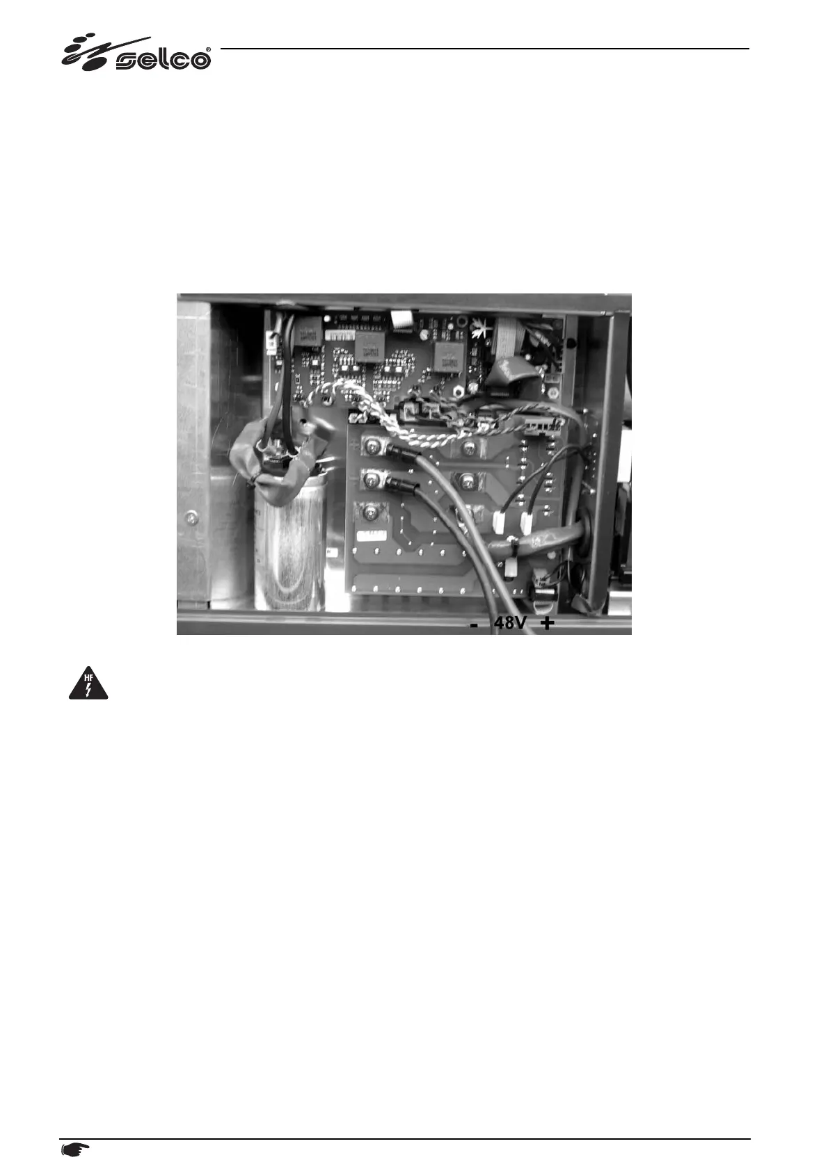
To test the operation of the inverter and secondary power rectifier safely, follow the following procedure:
- disconnect the power cables from C1 ("+" red) and E2 ("-" black) of IG2 and tighten the screws again
- isolate the 2 free connections coming from the levelling capacitor
- power the inverter power stage with an insulated external power supply source at low voltage and limited current (protected
against short circuits)
- switching the generator everything works normally but the output voltage reading must be appropriately scaled (e.g. by connec-
ting a +48Vdc external power supply to C1 and E2 you should obtain approximately 22Vdc no-load voltage when the torch trig-
ger is pressed).
ATTENTION! The external power supply source must be electrically insulated from the generator's 400Vac three-phase supply!
Attention! Before carrying out the above-mentioned procedure, disconnect the HF circuit (CN2 on board 15.14.192)
in order to prevent damages caused by HF discharges!
34 Description, testing and replacement of the electronic boards, current calibration
 Loading...