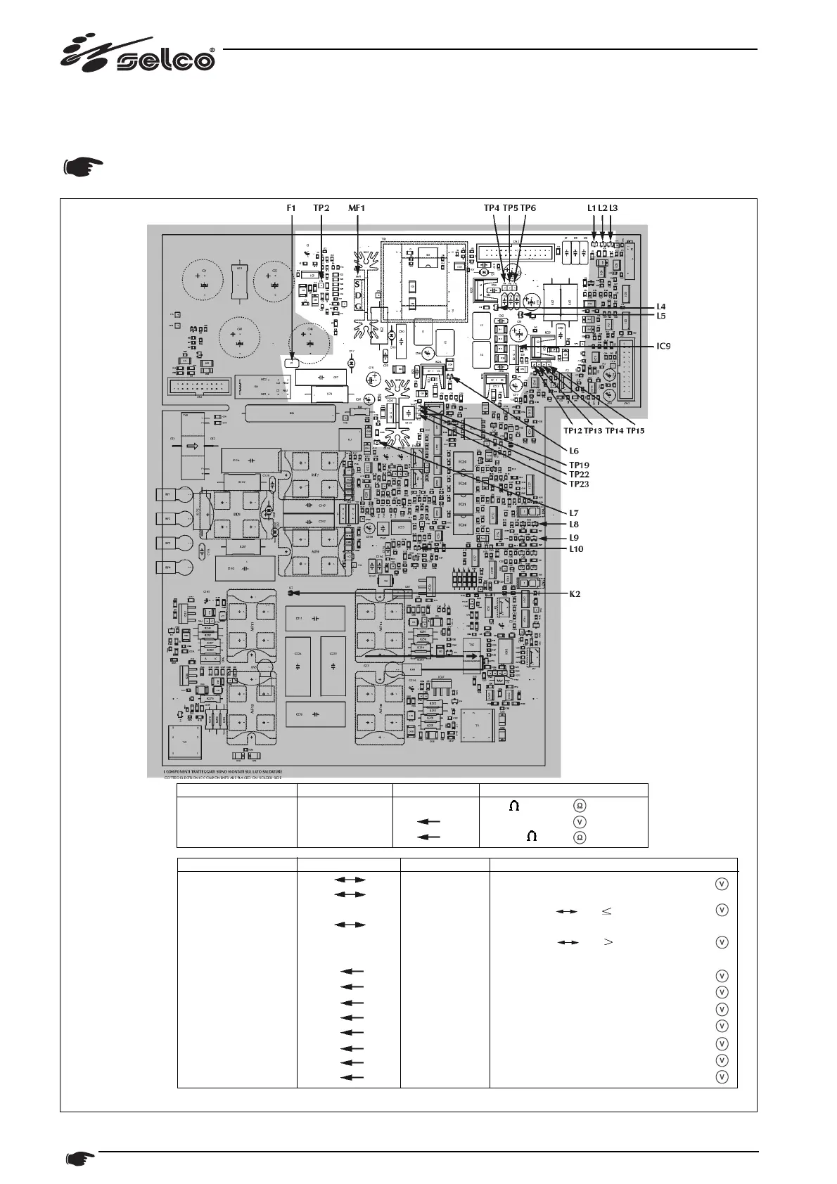
22 Description of boards
9.2.2) BOARD 15.14.250 "POWER SUPPLY SECTION" (fig. 18)
Switching power supply: supplies auxiliary voltage required for the whole machine to work. Generally, the various voltages
power circuits that are electrically insulated from each other (there is no ground shared by the whole machine).
WARNING: before taking measurements described, open solder-jumper K2 with the machine unplugged!
Power source / Mode Component Test point Value
OFF F1 - 0
OFF MF1 S D +0.4 Vdc
MF1 S G 10 K
Power source / Mode Test point Associated LED Value
ON RV1 RV2 - 230 Vac ± 20%
ON RV1 RV2 L8 OFF
(lit if V
RV1 RV2 184Vac)
ON RV1 RV2 L9 OFF
(lit if V
RV1 RV2 276Vac)
ON - L10 FAST BLINKING
ON TP13 TP15* L1 -15 ± 0.3 Vdc
ON TP14 TP15* L2 +15 ± 0.3 Vdc
ON TP12 TP15* L3 +5 ± 0.3 Vdc
ON TP4 TP6 L4 +24 ± 0.5 Vdc
ON TP5 TP6 L5 +48 ± 2 Vdc
ON TP19 TP22 L6 -15 ± 0.3 Vdc
ON TP23 TP22 L7 +15 ± 0.3 Vdc
ON TP2 TP22 - +14.5 ± 0.5 Vdc
* Note: for greater ease of measurement, TP15 is connected electrically to the metal TAB of IC9
Unless otherwise specified, all measurements sholud be taken with the boards in their slots and connected accordingly








 To Next Page