26 Wiring and connection diagrams
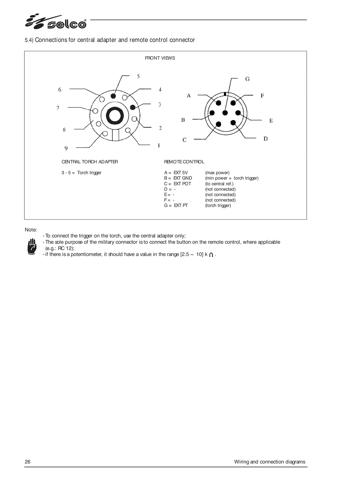
5.4) Connections for central adapter and remote control connector
Note:
- To connect the trigger on the torch, use the central adapter only;
- The sole purpose of the military connector is to connect the button on the remote control, where applicable
(e.g.: RC 12);
- if there is a potentiometer, it should have a value in the range [2.5 ~ 10] k .
FRONT VIEWS
CENTRAL TORCH ADAPTER REMOTE CONTROL
3 - 5 = Torch trigger A = EXT 5V (max power)
B = EXT GND (min power + torch trigger)
C = EXT POT (to central ref.)
D = - (not connected)
E = - (not connected)
F = - (not connected)
G = EXT PT (torch trigger)