14
4.
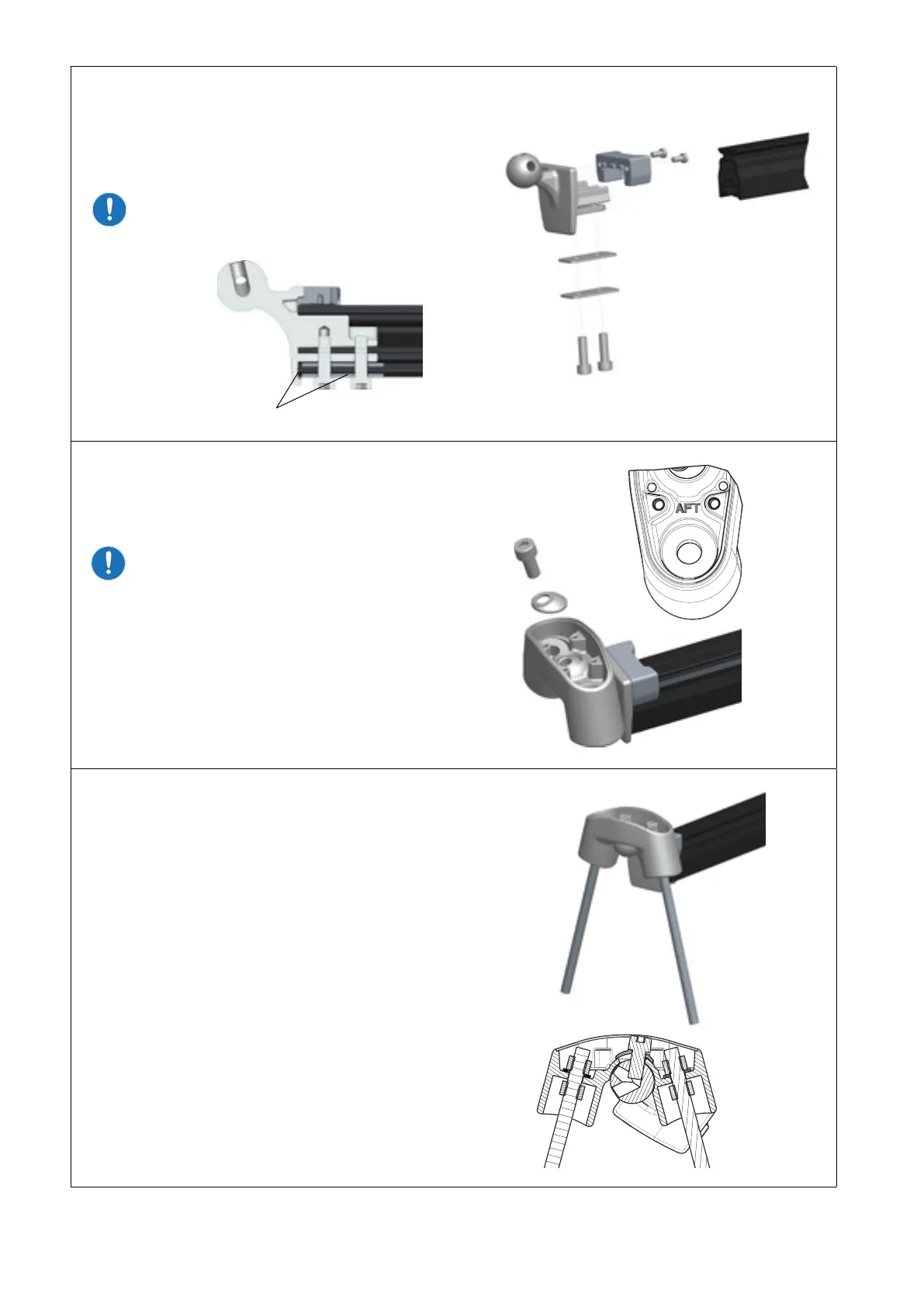
Install joint bracket 442-201 to both sides of the
track with the screws, washers and rubber end
stop. Use locking adhesive on the screws.
It is important that both washers are used
in the assembly, one on the outside and
one on the inside of the prole as shown.
5.
Assemble the bracket 442-200 with a screw and
spherical washer onto the joint bracket 442-201.
Make sure the 442-200 is assembled
on the correct side.
There is an “AFT” marking inside the bracket
442-200.
6.
Insert the M8 threaded bars into the brackets
442-200 and secure with washers and nuts
(none locking)
Place the system on deck according to the
marked position for the centre console and
adjust the threaded bars to approximately the
correct length.
Lock the position and angle of the four bars by
tightening the nuts (none locking).
Make sure there is a free area on the deck at the
end of each bar to install the deck ttings.
Foot kit 442-208-10
Cut threaded bar with over length to ensure
enough threads for deck thickness and
fasteners.
Washers