15
7.
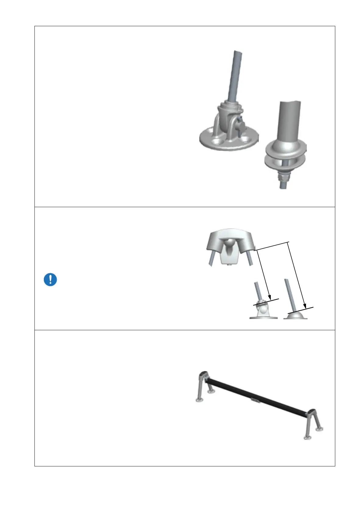
Deck tting 442-206-10
Screw the end tting 442-207 onto the ends of all
four treaded bars.
Assemble the complete deck tting kit as shown.
Place the system on deck with the deck ttings
attached and adjust the threaded bars to
correct length.
Mark the threaded bars 5mm above the nuts and
mark the position on deck or coach roof.
Disassemble the bars and cut to length at the
marked position.
Foot kit 442-208-10
Make an approximate mark of where the treaded
bar will intersect the deck. Use these marks as
reference for foot placement in step 8 when
deciding the length of the legs.
The position and nal length for the threaded bars
will be conrmed during installation.
8.
Measure and calculate the length of the legs
(Ø25mm tubes). Legs to be cut to L+23mm.
The extra 23mm will be hidden inside the
442-200 bracket when assembled.
Forward and aft legs might be dierent in
length. Make sure that the respective legs
on the opposite side are identical in length.
Cut legs with a hacksaw.
9.
Assemble the system and place on deck.
Ensure:
• The track is centred
• Track ends are symmetrical to forestay
• Track is in the correct angle for sheet
arrangement
Adjust side consoles so the deck ttings and
centre consoles are on the marked positions
on deck.
Check there is accessibility below deck to t nut
and washer.
L
L
Deck tting
Foot kit