CAUTION: Refer to the wire color codes and strictly adhere to this convention while connecting the charging
station and electrical supply wires. Incorrect wiring can lead to an electrical hazard.
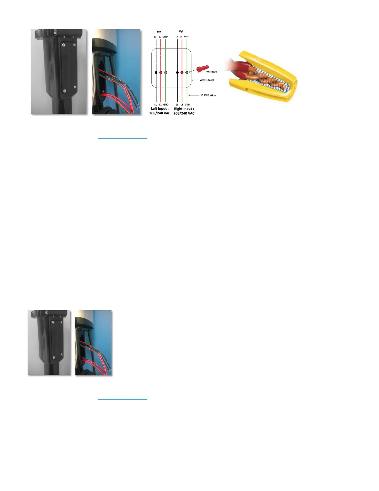
Connecting the Wires: Series 7 Plus
• Open the Access Panel by removing the four screws.
• Locate and access the wires inside.
• Carefully pull these wires a few inches outside of the access panel, to reveal 5 wires coming from the
Charging station Head Unit, Figure 21 (for Level-2 charging stations the color codes are Red, Black,
Red with Black stripe, Black with White stripe and Green) and 5 wires from the Pedestal with the
same color combination.
• Remove the insulation on each wire and prepare to connect those using wire-nuts.
• Match the wires using the colors (Black-Black, Green-Green & Red-Red) and connect them using wire
nuts as illustrated above.
• Also make sure that the striped wires are connected to the left side of the power source.
• Once connected, slowly insert the wires into the device and replace the access panel cover using the
screws previously removed.
CAUTION: Refer to the wire color codes and strictly adhere to this convention while connecting the charging
station and electrical supply wires. Incorrect wiring can lead to an electrical hazard.
Installation Manuals Series 7 / 7 Plus EV Charging Station - 1
Copyright ©2021 SemaConnect, Inc. All rights reserved. Page 25 of 26