Wireless & Sensing Products
Development Kit User Guide Rev.1.0
UG.DEV.SX1280-1.W.APP February 2017
3 of 15
Semtech
List of Figures
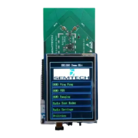
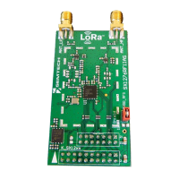
Figure 1: From left to right: screen, radio board and microcontroller MBED board ............................................................. 4
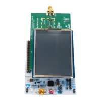
Figure 2: Screen, radio board and MBed board correctly assembled ........................................................................................ 4
Figure 3: Welcome Display ....................................................................................................................................................................... 5
Figure 4. PING PONG Demo Slave Display .......................................................................................................................................... 7
Figure 5: PING PONG Demo Master Display ....................................................................................................................................... 7
Figure 6: PER Demo Slave Display ......................................................................................................................................................... 8
Figure 7: PER Demo Master Display ...................................................................................................................................................... 8
Figure 8: Ranging Demo Slave Display ................................................................................................................................................ 9
Figure 9: Radio Settings Display in Ranging Demo ......................................................................................................................... 9
Figure 10: Ranging Demo Settings Display ........................................................................................................................................ 9
Figure 11: Ranging Demo Master Display before start ................................................................................................................. 10
Figure 12: Ranging Demo Master Display during test .................................................................................................................. 10
Figure 13: Radio Test Modes Display .................................................................................................................................................. 11
Figure 14: LORA Radio Settings Display ............................................................................................................................................ 12
Figure 15: FLRC Radio Settings Display.............................................................................................................................................. 12
Figure 16: GFSK Radio Settings Display ............................................................................................................................................. 13
Figure 17: Ranging Modem Radio Settings Display ...................................................................................................................... 13
Figure 18: Frequency Setting Display ................................................................................................................................................. 14
Figure 19: Utilities Display ...................................................................................................................................................................... 14