1l>'l.1l'l'U'IC)', 100V·.IV
RI'.t
JO
MH.
.
1'lo,UmV·IOVIX;
1'i,0-2VACRMSatlOOOHz.
.$OQ VRMS t
I~
at 1000 HI.
3.00
WRF
t5'J,
..
27
MHz.
-
The
Block
Diagrlm
of
the
CB42 is
.hown
in Fig. 61
Elch
01
thoe
M(1.ionI
in
the block
dilgrlm
is iIollted.
from
the
other
~ionlwith
PO"'"
IUpply
filterin,.nd
electriall ahieldinc.
This
reullll
ill very little interfem1Cl!
COMPlETE CIRClIT DESCRIPTION
The c:omplete circuit de8criptioa for the CB42, with
simplified circ:uil
d~
ill
....
i1.bIe for 15.00
han-
ACCESS/OtSASSEMBLY
To
pin
~
1O
the
interior
of
the
C842
for
!Min.
tenarooe
Gr
calibration, follow thill
pro<.-..:!u,."
I,
Rano"e AC Jl'O"er from
the
CB42
by
dilconl\ElCtin,
it
from
thoe
AC
line.
2.
Remove
the
lis
8CreWI
in
the
bottom
p.nel
Ind
slide the panel
toward.
the
~r
of
the
unit
to
remove
it.
J.
Remove
the
two
&o:rews
on either side of the
cue.
CALIBRATION PROCEDURE
The
calibr.tion
of
the
CB42 should he cllecked
at
regu-
I.,
intervallto
make
lu,e
it is within original accuracy
"JI""iflCationa.
It
1$
recommended
that
any unit requiring
n'Clllibflltion be
returned
to
one
ot
the
$encore
Sal"
and
5erva
OfflCell
listed
in
the illlide back cover
of
the
minuli.
If
field calibration is
d~ired,
follow the
..
epl!
listed below,
POWER
SUPPL.
V
I. MealUre ripple
00
10 volt
output
of
POW" ItIpply
PC
bo
..
d..
Should indicate I
....
than
30
mY.
2.
Meallllre ripple
on
5 yolt output otJlO"'er ItIpply
PC
board.. Should
indiate
1_
than
30
mY.
J.
Monitor
DC
yoltage
of
10
'·olt
OU\Jlllt
of
power 1tIp.
ply
PC
board.,
Set
10 Volt
Adjust
(RI04)
for 10.00
V *
0.1
VDC.
SCOPE
ADAPTER
I.
Feed 26.9% MHz (CB channel
I)
into 50
ohm
in.
"'''
2.
Connect KlIJIe 10
S<:ope
Adapter output.
J. Set Scope Adapter Frequency
Adjult
{or
zero-beat
on 1l'Op&.
4.
Hndjult
L701
for 40 KHz output
011
KOpl',
5.
Switch Rr inllllt
to
26.975 MHz (CB channel
2).
F'nqu.,ncy
on
IleO""
should ;n\:rease.
If
Channoel
2
(~u""CY
is lower
than
t:hanllell
frequency. repeat
~t'lp
4 tor
.0
KHz signal
on
oppollite side of ,ero-
..
"
..
between sectiona. Thill dellign
I~
11110
I\lOWS
Iny
ciuuit
troublellhootin,10
qukkly
illollte I
mllfundion
to
I lIin,le circuit
oo.rd
by
injectin,.iglUlb
or
monitor·
ing .iKn.11 U the front panel input/output
jacb.
dlinc
chaT):e from the
Selloo",
Field
Encu-ring
Dreplrt-
ment.. 3200 Scnoo,., Drive, Sious
Falil,
S.D. 57107.
and
the two ac:rewl
on
the
top
of
the
cue.
RelJll,7Ve
the
atle
b)'sliding
it
towarth
the
~r
of
the
unit..
As
the
caW!
ill
rell>O\'ed,
feed the
AC
cord
throu&h
the
hole
in
the
cue
until
the
cue
is
dear
of
the
unit.
•.
Complete._
is
avail.ble
for calibrating
the
CB42 without further dilaMembly.
5.
To
rea_mble,
.imply
,tweflle
the
stepll
above.
EQUIPMENT
REQUIREMENTS'
EQUIPMENT SPI::CIFICATIONS
F=lu<'fIC)' coun!<'r
,OlIO
I
~
(l
ppm)
"
F=lu<'fIC)'
lIUnd.nl
RF
Voluneto>.
IX;
Volwp
Sou,
...
AC Voluneto>r
AC
Sienal
Sou,.,.
RI'
"-Sou
.....
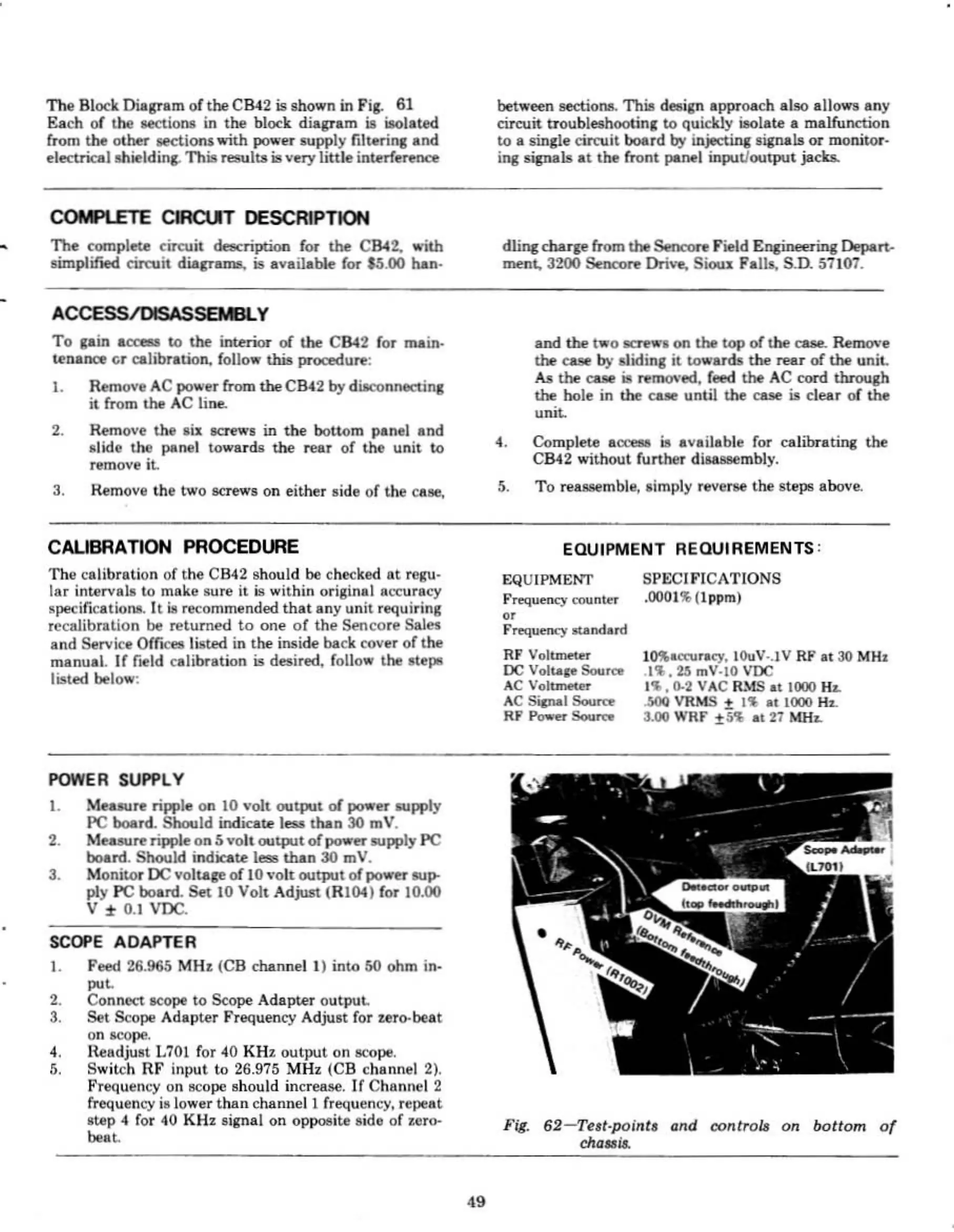
i'i8.
62-Terl·poinla
ond
controls
On
bottom
of
cho.,~
•