PRODUCT INSTRUCTION MANUAL
Page 11 of 35
Part 4 Transmitter Electrical Installation
4.1 General
The TX100 loop-powered instrument is a 12-24 VDC loop-powered pH/mV transmitter.
WARNING: Do not connect AC line power to the 2-wire module. Severe damage will result.
Important Notes:
1. Use wiring practices that conform to all national, state, and local electrical codes.
2. DO NOT run sensor cables or instrument 4-20 mA output wiring in the same conduit that contains AC
power wiring. AC power wiring should be run in a dedicated conduit to prevent electrical noise from
coupling with the instrumentation signals.
3. DO NOT remove dessicant pack from inside transmitter case. This is necessary to control moisture.
4.2 Power
A12-24VDC power supply, eight amp maximum current must be used to power the instrument. See chart
below for Maximum load. The exact connection of this power supply is dependent on the control sys-
tem into which the instrument will connect. See Figure 4.1 for further details. Any twisted pair shielded
cable can be used for connection of the instrument to the power supply. Route signal cable away from AC
power lines, adjustable frequency drives, motors, or other noisy electrical signal lines. Do not run sensor or
signal cables in conduit that contains AC power lines or motor leads. The TX100 is supplied with a light-
ning protective component.
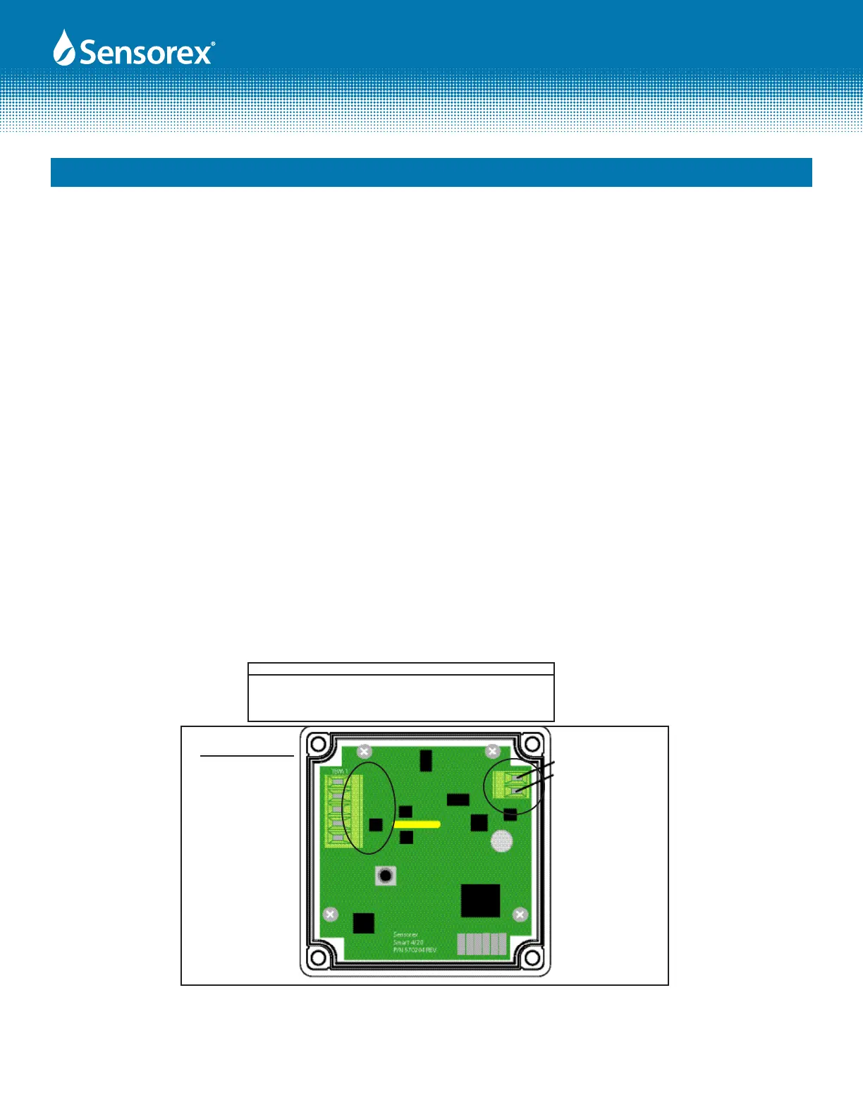
Note: Terminal block labels for power, electrode and temperature sensor connections are marked on the PCB next to their
respective terminal.
Figure 4.1
PB
RF
GD
TC
PWR
Supply Voltage( V DC) Max Resistance Load (Ohms)
12 150
16 350
20 550
24 750
TBM1 - Terminal Block
1. PB, pH wire (center wire of
coaxial cable)
2. RF, Reference wire (braid of
coaxial cable)
3. GD, Temperature Input 1
(Pt1000 RTD)
4. TC, Temperature Input 2
(Pt1000 RTD)
5. PWR (NO CONNECTION)
1. (L-) Power Supply -
2. (L+) Power Supply +