PRODUCT INSTRUCTION MANUAL
Page 13 of 35
Part 5 Electrode Electrical Connection
5.1 General
The electrode cable can be quickly connected to the TX100’s terminal strip by matching the wire colors on
the cable conductors. Route signal cable away from AC power lines, adjustable frequency drives, motors, or
other noisy electrical signal lines. Do not run sensor or signal cables in conduit that contains AC power lines
or motor leads.
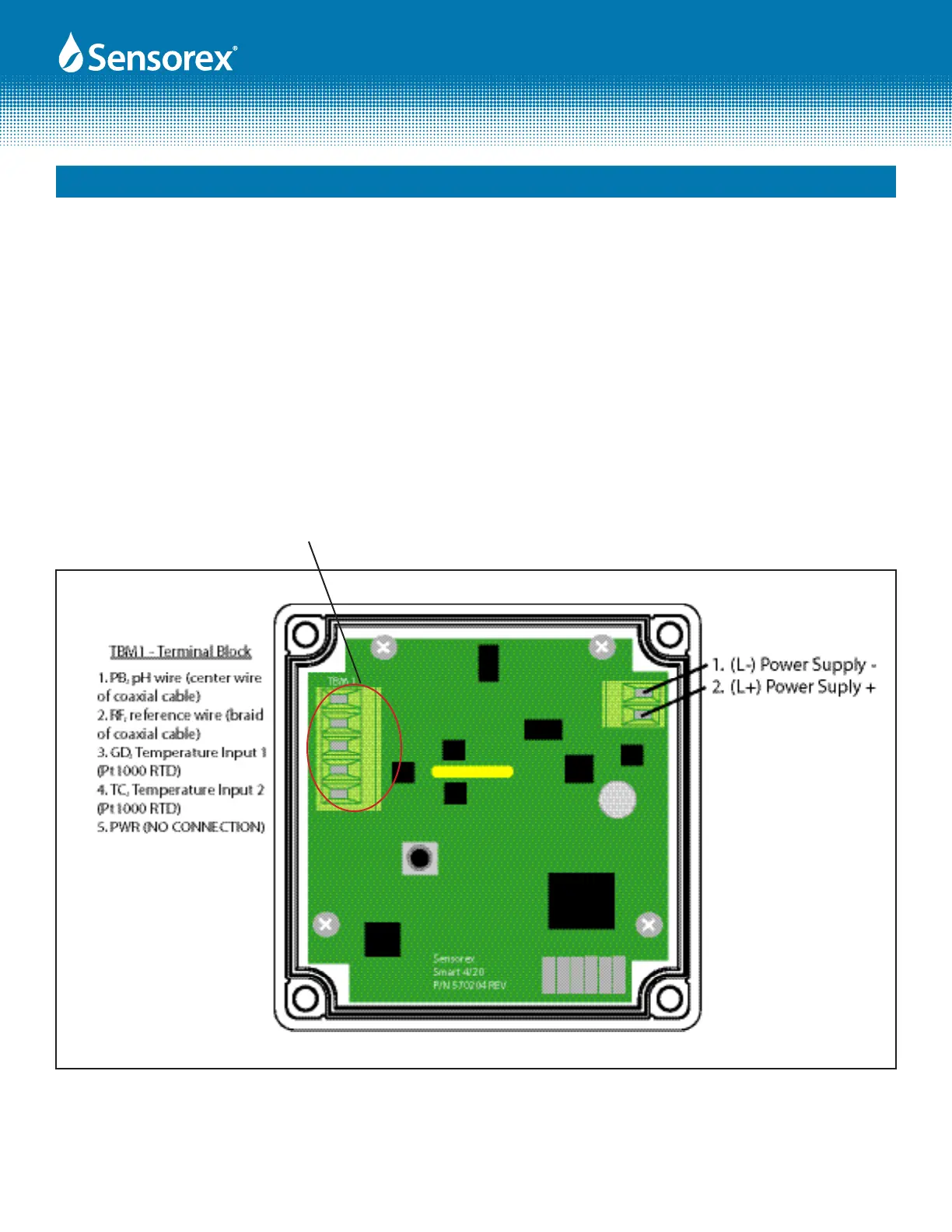
5.2 Direct Sensor Connection
The sensor cable can be routed into the enclosure through one of the provided cord-grip retainers, or
through a properly sized conduit connection. Connect electrode wires as shown below.
If the cord-grip devices are used for sealing the cable, ensure the cord-grips are snugly tightened after elec-
trical connections have been made to prevent moisture incursion.
Note: Terminal block labels for power, electrode and temperature sensor connections are marked on the PCB
next to their respective terminal.
Figure 5.1
PB
RF
GD
TC
PWR