PRODUCT INSTRUCTION MANUAL
Page 12 of 35
Part 4 Transmitter Electrical Installation
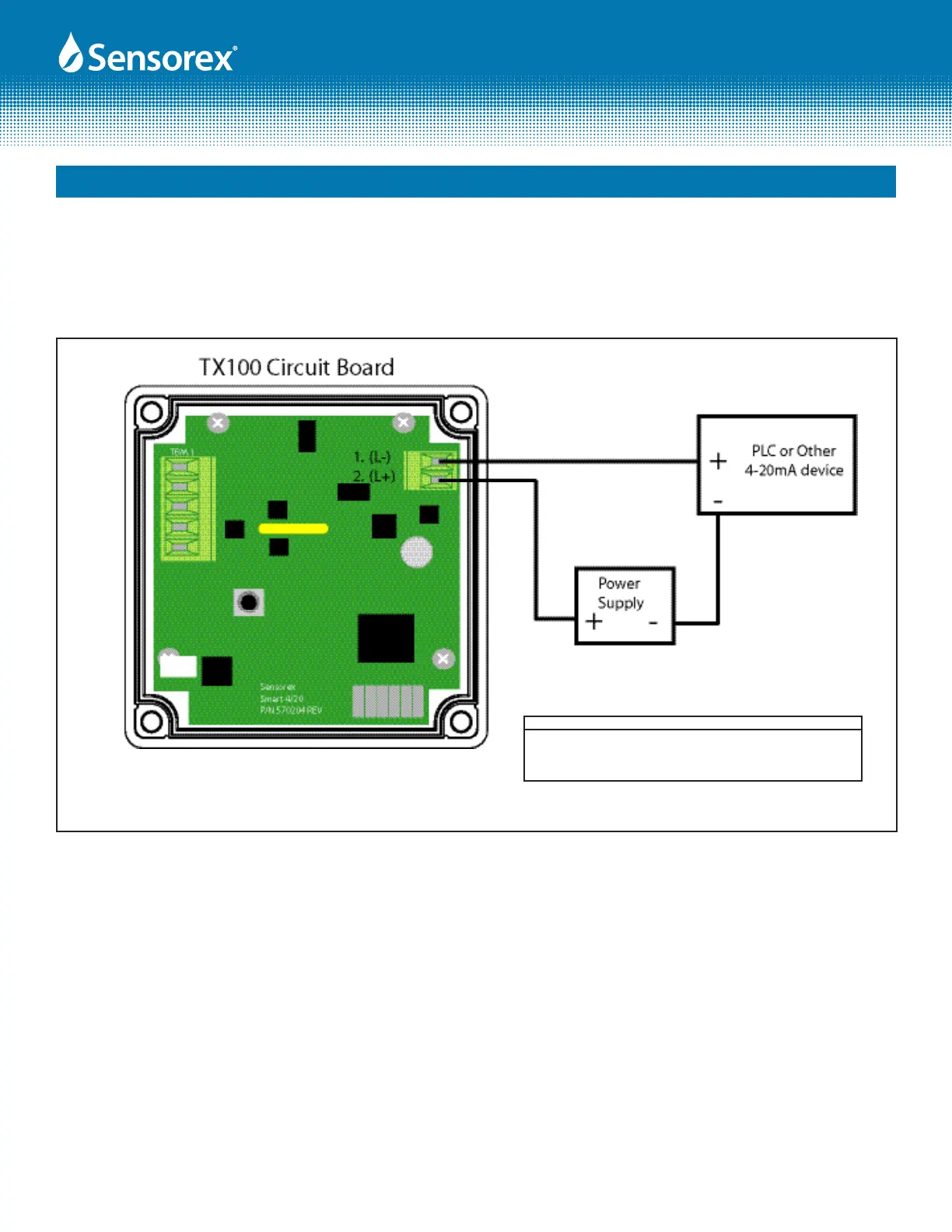
Figure 4.1A
Supply Voltage( V DC) Max Resistance Load (Ohms)
12 150
16 350
20 550
24 750
4.3 4-20mA loop connection to PLC or other 4-20mA load device
Install loop wiring as shown below in diagram 4.1A, paying particular attention to maximum resistance load
shown in the chart. Note that PLC or 4-20mA device and power supply are customer supplied components.