PRODUCT INSTRUCTION MANUAL
Page 29 of 35
Part 10 Troubleshooting
10.1 General
The information included in this section is intended to be used to quickly resolve an operational problem
with the system. During any troubleshooting process, it will save time if the operator can rst determine if
the problem is related to the transmitter, electrode, or some external source. Therefore, this section is orga-
nized from the approach of excluding any likely external sources, isolating the transmitter, and nally isolat-
ing the electrode. If these procedures still do not resolve the operational problems, any results noted here
will be very helpful when discussing the problem with the factory technical support group.
10.2 Troubleshooting Guidelines
To begin this process, review the connections of the system to all external connections:
1. Verify the proper power input is present (12-24V DC, 8 amp maximum). Ensure the loads on the
4-20 mA outputs do not exceed the limit (See Section 4.2) .
2. Do not run sensor cables or analog output wiring in the same conduits as power wiring. If low
voltage signal cables must come near power wiring, cross them at 90° to minimize coupling.
3. Check for possible ground loops. High frequency sources of electrical noise may still cause erratic
behavior in extreme conditions. If readings are very erratic after wiring has been checked, check
for a possible AC ground loop by temporarily moving the sensor to a sample of solution in a
beaker or other container.
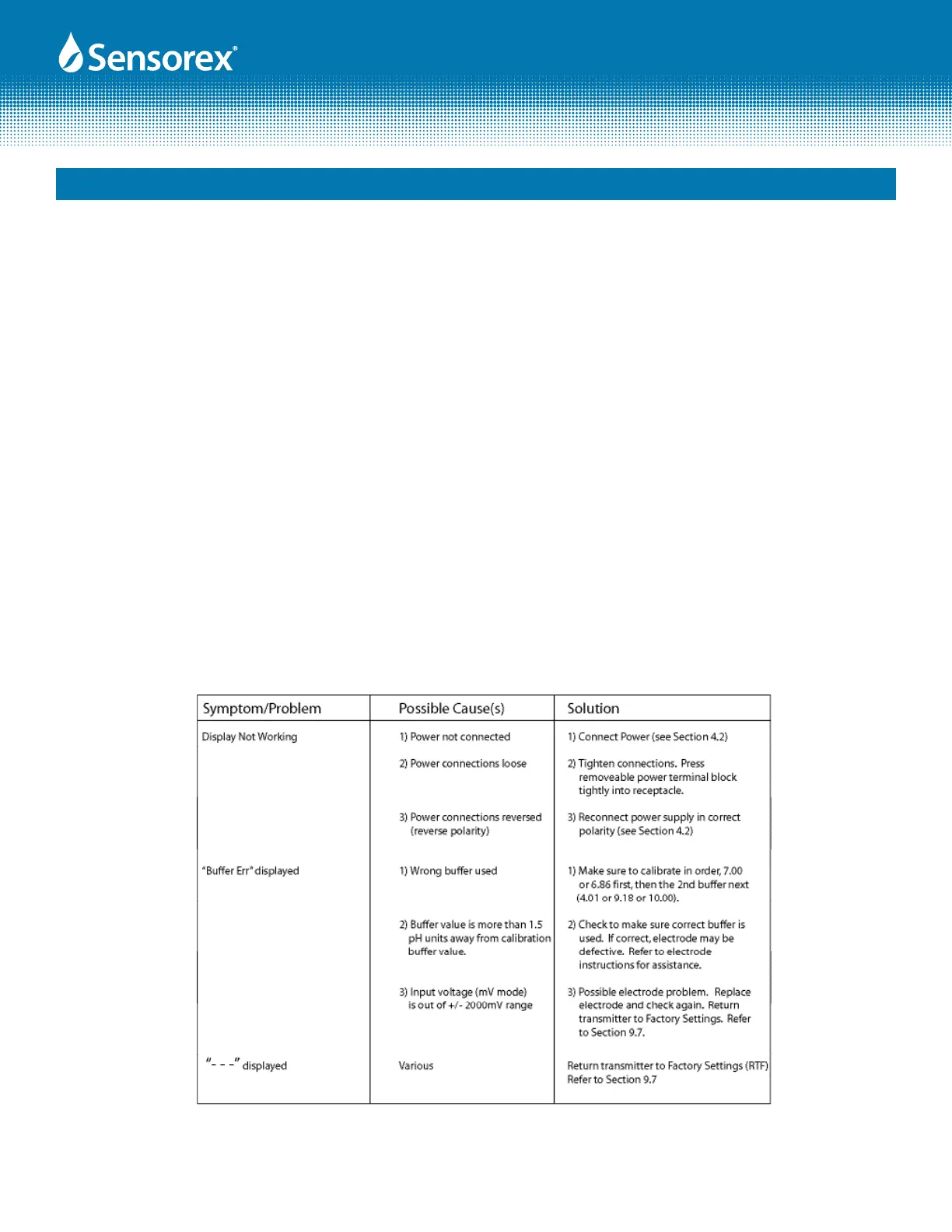
10.3 Troubleshooting Chart TX100
Figure 10.1