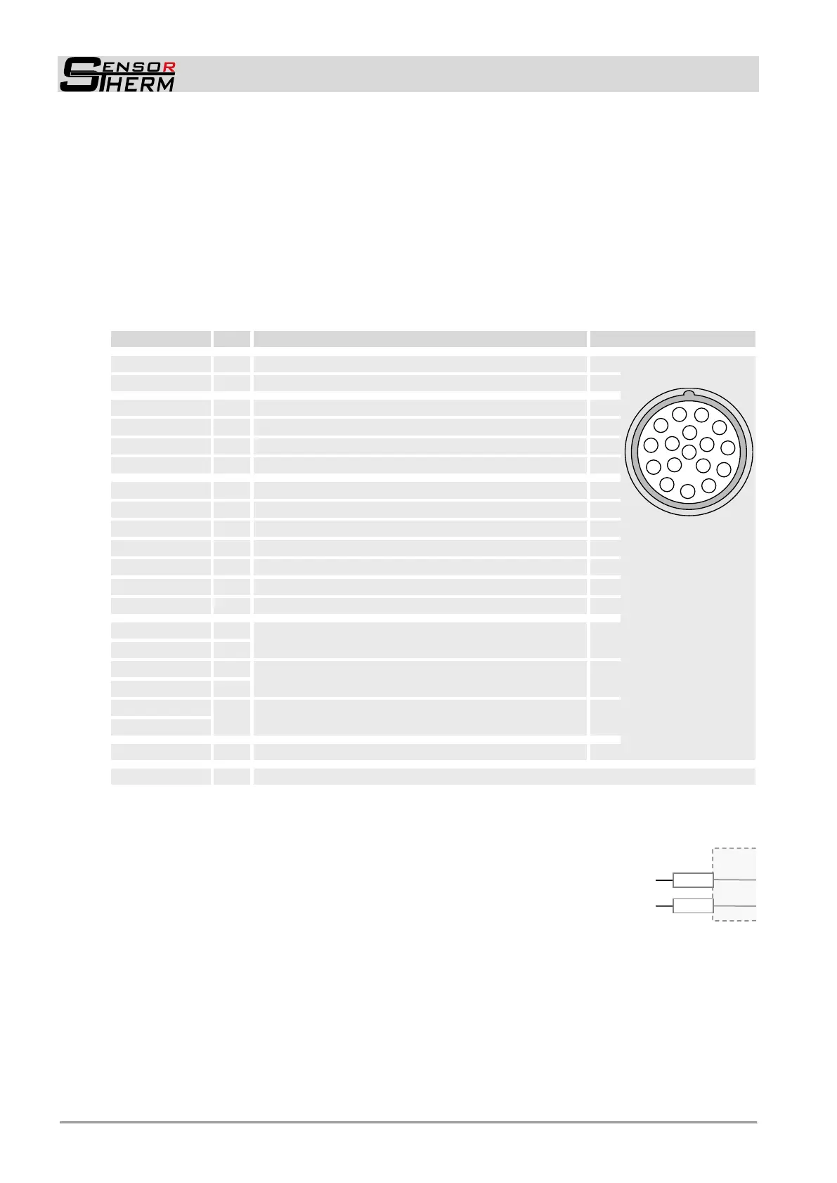
METIS M311 / M322 / H311 / H322 (17-pin)
Electrical Connection
8
4 Electrical Connection
4.1 Cable Colors and Pin Assignment
The electrical connection of the pyrometer (supply voltage and measuring signal) will be done via the
17-pin connector on the device’s rear side. For this purpose, pre-assembled connection cables are
available as accessories (cables 20-wire + shield, with straight connector and optionally with integrated
USB interface converter, see 9.4 Accessories).
Note: The unit has 3 separate circuits: supply, interface and power outputs. The reference potentials
GND should not be connected together. To prevent accidental short circuits, cable wires not in use
should be secured to the supplied screw terminals.
+ 24 V DC Power supply (18–30 V DC)
7
8
9
10
11
5
6
4
3
2
1
12
13
14
15
16
17
View from outside
to the 17-pin
device plug
+ Analog output 1 (0 / 4–20 mA)
- Analog output 1 (0 / 4–20 mA)
+ Analog output 2 (0 / 4–20 mA)
- Analog output 2 (0 / 4–20 mA)
RS232: RxD
RS485: B (+)
2)
RS232: TxD
RS485: A (-)
2)
DGND (ground for interface)
Reference voltage output (10 V ±1%, max. 10 mA)
1)
Shield (connect only for cable extension, do not connect in the control cabinet)
1)
Reference potential 0 V, brown
2)
H3 models only RS485
4.1.1 Power Supply
With connection of the supply voltage (standard 24 V DC, possible range 18–
30 V) the unit is ready for operation with the following factory settings (chang-
ing the settings is possible via interface and Software SensorTo ols, see 7).
The supply voltage must be protected with a slow-blow fuse of 800 mA.
Interrupt the power supply to turn off the pyrometer, e.g. by disconnecting the connector.
 Loading...