METIS M311 / M322 / H311 / H322 (17-pin)
Electrical Connection
11
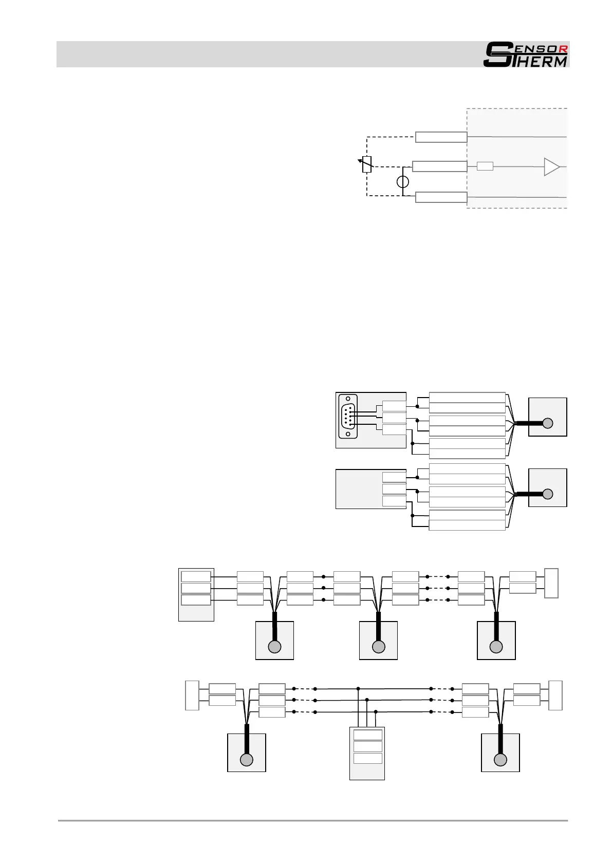
Setpoint input via external voltage 0...10 V: This voltage
can also be made via the 10 V reference voltage output
and a 2 kΩ potentiometer (connected as a voltage divider,
the internal resistance of the input is 40 kΩ).
Internal resistance
40 kΩ
Analog input (input 5):
About a 0-10 V supply it can be adjusted ex-
ternally:
- The emissivity slope
(0 V = 0.8; 10 V = 1.2)
- The emissivity for every channel
(0 V = 0.05; 10 V = 1.2)
- The setpoint for PID controller
(0 V = zero scale temperature,
10 V = full scale temperature)
- Measuring distance at M3 devices with mo-
torized focus (0 V = shortest distance, 10 V
= widest distance)
4.1.4 Serial Interface RS232 / RS485 (M3: switchable RS232 / RS485; H3: only RS485)
The serial interface is used for digital communication of the pyrometer with another computer, for exam-
ple a PC for data transmission to the software SensorTools. Via interface always all temperatures are
transferred (2-color and one channel temperatures) as well as device information and parameters.
The maximum transmission speed (in Baud) is limited by the cable length, it is halved with each dou-
bling of the transmission path.
RS232: about 7 m cable length with 19.2 Bd. Adjustable are values from 4.8 to 115.2 kBd.
RS485: about 2 km with 19.2 kBd. Adjustable are values from 4.8 to 921.6 kBd.
Connecting one pyrometer via
RS232 or RS485:
In a short RS232 or RS485 connection to the mas-
ter (computer receiving the data), the pyrometer is
connected directly as a point-to-point connection
with the master.
It is advantageous to connect all interface cables
in order to avoid reflections.
Connecting several pyrometers via RS485:
For a reflection-free operation with longer cables, pay attention to the correct cable termination. Termi-
nation at the physical bus is at the beginning and at the end.
Master at
the beginning:
Master in
the middle:
Terminating
resistor 120 Ω
Terminating
resistor 120 Ω
in the master
or manually
Terminating
resistor 120 Ω
Terminating
resistor 120 Ω
 Loading...