Rev B Doc 6001564 Page 3 of 19
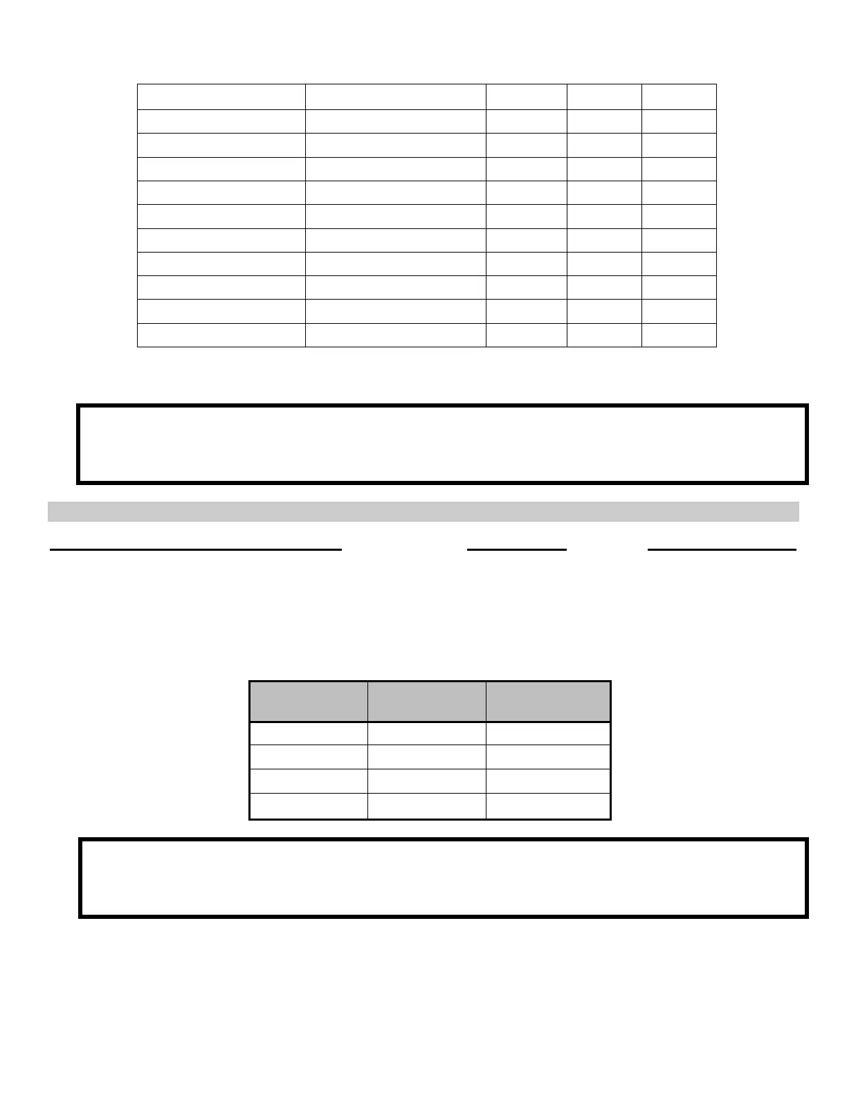
1. CABINET DIMENSIONS
TYPE OF SYSTEM
HEIGHT WIDTH DEPTH
Infinity “L” or “DI” Surface Mount 21.0” 16 7/16” 4 1/4”
Flush Mount Back Box 21 1/4” 16 3/4” 3 3/16”
Flush Mount Bezel 23 11/16” 19 3/16”
Infinity “M” Surface Mount 16.0” 11 3/4” 4 1/4”
Flush Mount Back Box 16 7/16” 12 1/4” 3 1/4”
Flush Mount Bezel 18 3/4” 14 1/2”
Infinity “S” Surface Mount 16.0” 11 3/4” 3 1/4”
Flush Mount Back Box 16 7/16” 12 1/4” 2 1/4”
Flush Mount Bezel 18 3/4” 14 1/2”
Infinity “B: 23.0” 14.0” 2 3/4”
2. WIRE CHART
PLEASE NOTE: If the wires you are pulling for this installation are going to be run through an indoor,
weather-proof location, it is acceptable to use unshielded cable. If the wires are going to be run through
an outdoor location, we recommend that you use shielded cable. Recommendations for both types of
cable are provided where needed.
A. CABLING TO THE MAIN PROCESSOR BOARD
Cabling to the Main Processor Board Type of Wire Recommendations
From the power transformer or power supply 2 conductor cable See chart below:
120 VAC outlet
From the door strike or the door strike 2 conductor cable See specifications for
power supply the device you are
installing.
DC POWER
WIRE SIZE
DISTANCE AC POWER
WIRE SIZE
18 AWG 30' and under 14 AWG
16 AWG 30'-75' 12 AWG
12 AWG 75'-150' -----
10 AWG 150'-250' -----
PLEASE NOTE: If you are using the larger sizes of cable (i.e., 12 awg or 10 awg), you may experience
problems inserting the wires into the terminal block. If you encounter this problem, you can connect a
16-18 awg wire (with the use of a wire nut) to each end of the power cable, as long as the smaller gage
wire is under 12 inches in length.