Do you have a question about the Sentry Sample Sentry II Low Pressure and is the answer not in the manual?
Explains signal words for hazard identification.
Defines hazard terms like DANGER, WARNING, CAUTION, NOTICE.
User responsibility for product selection, maintenance, and intended use.
Highlights hazards like hot surfaces and high pressures.
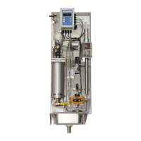
Describes product purpose and available LP/HP models.
Details flow control range/accuracy and pressure measurement specs.
Specifies temperature measurement ranges and alarm contact ratings.
Lists power input, compressed air needs, and unit dimensions.
Explains why constant flow is vital for sample quality.
Describes automated flow control using PRV and sensors.
Explains controller buttons: MENU, ENTER, ESC, Arrow keys.
Illustrates the controller menu structure and navigation paths.
Details operational states (Start, Blowdown, Sample, Stop) and modes.
Explains alarm display and reset procedures, focusing on High Temperature Alarm.
Describes motor alarm causes and troubleshooting steps.
Guides through main menu access and password entry.
Describes how to adjust the display intensity using arrow keys.
Details navigation and configuration options within the setup menu.
Configures blowdown, sample, and shutdown flow rates.
Sets the duration for the blowdown state.
Covers additional setup parameters.
Configures startup and shutdown pressure thresholds.
Explains PRV type, start position, and recalibration procedures.
Sets the frequency for automatic VREL valve cleaning.
Guides through second set of setup options including Alarms, Units, Options.
Configures alarm conditions like Outlet Temperature and Low Flow.
Allows switching between English and SI units.
Enables or disables optional measurement inputs.
Configures MODBUS address and BAUD rate for system communication.
PID parameters are password protected and require Sentry assistance for tuning.
Accesses calibration and setup for analog inputs.
Covers inspecting the unit and mounting it to a wall.
Details the required connections for water, sample, drain, and air.
Describes power supply requirements and electrical connection safety.
Step-by-step guide for powering up and initializing the system.
Discusses descaling and disassembly of the sample cooler.
Covers VREL/Needle valve blockages and inlet isolation valve packing.
Notes that only the diaphragm is serviceable for the BPR/RV.
Explains how particulates can lodge in the sample valve plunger.
Describes replacing the packing in the sample shutoff valve.
Emphasizes care during flow transmitter removal and installation to prevent tube damage.
Step-by-step guide for installing the VREL coupling.
Step-by-step guide for installing the Needle Valve coupling.
Details fuse replacement and general controller disassembly procedures.
Detailed steps for calibrating analog input channels.
Advises consulting the factory for flow meter calibration.
Lists default configuration values for various parameters.
Provides solutions for elevated temperature, reduced flow, leaks, and motor alarms.
Addresses issues with a PRV shaft that will not turn.
Lists spare parts with descriptions and Sentry P/N for ordering.
Lists P/N for controller, CPU board, output board, and display board.
Outlines warranty periods for Sentry and Waters Equipment products.
Lists customer support services including technical, installation, and field service.
Explains MODBUS setup and lists communication registers.
Details specific MODBUS register functions like State and Remote Control.