Do you have a question about the Serpent Viper 988e and is the answer not in the manual?
Covers critical safety guidelines for building and operating the model.
Attaches initial components to the rear chassis plate.
Assembles the rear suspension arm components.
Sets up the rear antiroll bar with specific length.
Installs parts for the rear drive system.
Mounts the belt for the rear drive system.
Highlights notes regarding rear axle excenters' symmetry.
Adjusts the belt tension for the rear drive.
Attaches brackets to the rear chassis.
Fine-tunes the rear antiroll bar play.
Installs various components of the rear drivetrain.
Adjusts the rear track width of the car.
Configures the rear camberlink length and position.
Attaches initial components to the front chassis plate.
Installs parts for the front drive system.
Adjusts the belt tension for the front drive.
Assembles the front suspension arm components.
Assembles the front anti-roll bar system.
Installs inserts into the front suspension.
Configures the servosaver ackermann inserts.
| Category | Motorized Toy Car |
|---|---|
| Brand | Serpent |
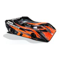
| Model | Viper 988e |
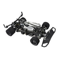
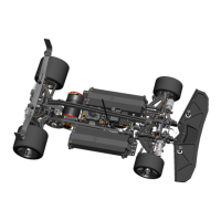
| Drive | 4WD |
| Suspension | Independent, double wishbone |
| Motor | Not included |
| ESC | Not included |
| Battery | Not included |
| Differential | Ball Differential |
| Body | Not included |