6
Installation Instruction
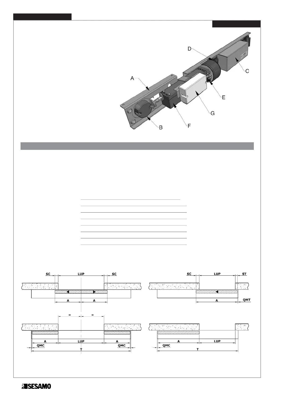
The integrated movement control module (Fig. 3)
is essentially made up of:
A. Base support plate
B. Encoder unit with belt adjustment device
C. Electronic control panel
D. Transformer
E. Mains connection terminal board (230Vac)
F. Emergency battery (optional)
G. Safety electronic key decoder (optional)
Automatism girder assembly
Positioning quotas
The automatism must be centred to the transit area in two-wing cross-pieces so that the wings meet in the middle of the
light space (Fig. 4).
For single wings observe the indications and machine quotas found in Fig. 5.
Cross-pieces with extensions (any unused box areas) should be positioned with the extensions summing QMC and QMT.
For the abbreviations found in Fig.4 and Fig.5 refer to the following table:
Lup: Working transit width
A: Sliding wing width
St: Top wing clearance
Sc : Bottom wing clearance
T : Total box length
QMT : Top machine quota (5mm)
QMC : Bottom machine quota (5mm)
Fig. 4 Fig. 5
Fig. 3
LIGHT MILLENNIUM