Technical Setup • Super II 87
Soft Key:
ALARMS
Setting Up the Alarm Outputs
The controller has three digital alarm outputs that can be used to control an external system. The alarm
output pins are located in the OUT port. The state of the alarm is based on the weight of the scale relative
to the set points (see the SETPOINTS soft key in the USER’S MANUAL). The alarm pins are held at either
Ø volts (LO) or 5 volts (HI).
There are three set points that the operator can program: Low, Target and High. The set points can be
programmed to any weight as long as the Low set point is lower than the Target set point and that, in turn,
is lower than the High set point. The three set points create four weight regions. Region 1 covers all
weights lower than the Low set point. Region 2 is between the Low and Target set points. Region 3 is
between the Target and the High set points. Region 4 covers all weights greater than the High set point.
Each alarm can be programmed to be either LO or HI in each of the four regions.
The alarm can be configured to be either latching or non-latching. When in the latching mode, once an
alarm output has changed state, it will remain in the new state until a reset signal is received (the reset
signal can be sent through the digital inputs, the keypad, or an SDL command).
When the alarms are programmed, the user menu selection SETPOINT changes to ALARMS. The functional-
ity of the SETPOINT remains in the menu selection, but extra controls are added for operating the alarms.
See the “User Manual” for further details.
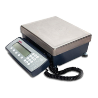
To access the ALARMS menu, follow the menu tree or press the keys in the order listed below:
Choose from the options below:
SETUPS
MORE
TECH
SETUP
MORE
ALARMS
abc reset
tare
menu remote
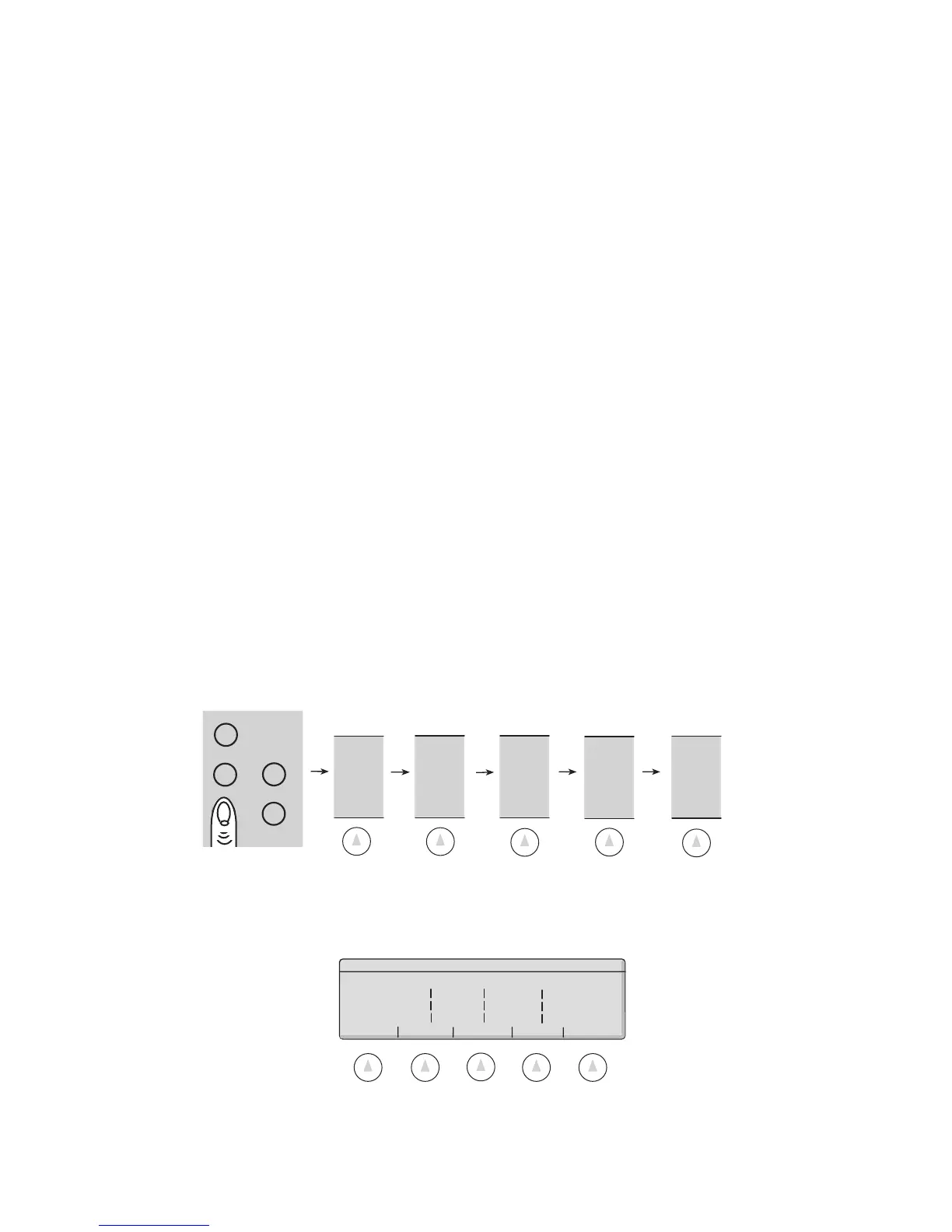
Alarm Outputs:
LOW TARGET HIGH LATCH
ALARM 1 LO HI HI HI
ALARM 2 LO LO HI HI
ALARM 3 LO LO LO HI
ENABLE DISABLE PROGRAM GO BACK
 Loading...