3
Device structure
Electronics
Operating Instructions – MOVIMOT
®
flexible
24
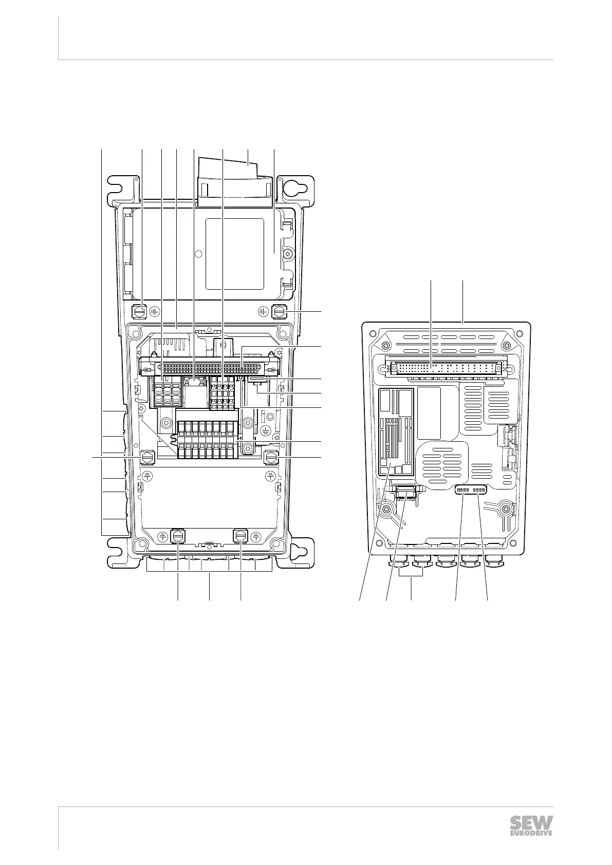
Design MMF3.
The following figure shows the connection box and the bottom side of the electronics
cover:
S1 1 2 3 4 1 2 3 4 S2
OnOn
D C B A1 T2 U V W
[4][3][2] [6]
[9]
[5] [7] [8][1]
[14]
[1]
[3][3] [15][16]
[3][3]
[3]
[10]
[11]
[12]
[9]
[13]
[18] [12][17]
27021623563981707
[1] Cable glands [10] Engineering interface
[2] Screws for PE connection [11] MOVILINK
®
DDI connection
[3] Connection line L1, L2, L3 [12] Fieldbus connection (depends on the configured
connections)
[4] Connection box
[5] Braking resistor connection [13] Connection for motor, brake and temperature
sensor
[6] Electronics terminal strip [14] Electronics cover
[7] Maintenance switch [15] DIP switches S1/1 – S1/4
[8] Front module [16] DIP switches S2/1–S2/4
[9] Plug connector connection unit for electronics
cover
[17] Replaceable memory module
[18] Electronics cover nameplate
29128668/EN – 12/2019
 Loading...


