Do you have a question about the SEW-Eurodrive MOVIMOT advanced DRN DBC Series and is the answer not in the manual?
| Brand | SEW-Eurodrive |
|---|---|
| Model | MOVIMOT advanced DRN DBC Series |
| Category | DC Drives |
| Language | English |
Outlines the user's responsibilities for safety compliance and qualified personnel.
Specifies the intended installation and use of the product.
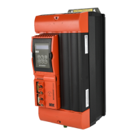
Illustrates the inside of the electronics cover and the connection box with numbered parts.
Provides essential safety warnings and notes for installation.
Focuses on arranging and routing components for EMC-compliant installation.
Shows the basic installation topology with MOVIMOT® advanced, including safety relay and control connections.
Shows the terminal assignments for the MOVIMOT® advanced drive unit.
Details terminal assignments for control terminals X9 and engineering interface X31.
Provides the connection diagram for the MOVIMOT® advanced drive unit.
Warns about safe disconnection and provides connection details for STO function.
Warns about disabling safety functions and provides connection details for STO function.
Provides essential safety warnings and notices for the startup procedure.
Includes notices about switch-off times and information regarding LED displays and nameplates.
Lists conditions for startup, including correct installation, project planning, and safety measures.
Lists required hardware and software components for startup.
Explains Easy mode and Expert mode for device parameterization.
Provides an overview of the control elements on the electronics cover, including potentiometers and DIP switches.
Provides notices regarding DIP switch handling and overview of DIP switches S1, S2, S3.
Describes startup without PC or keypad, using mechanical elements and FCB 05.
Describes startup in Expert mode using MOVISUITE® engineering software.
Illustrates the startup procedure in segments and provides a checklist for complete startup.
Explains intuitive startup guided by symbols and functions on the CBG21A keypad.
Shows the CBG21A keypad layout and explains operation for activating fields and entering numbers.
Explains startup using the CBG11A keypad, noting limitations with encoders.
Shows the CBG11A keypad layout and explains operation for selecting functions and entering numbers.
Explains configuration of digital inputs and outputs in Easy and Expert modes.
Details setpoint scaling for analog input AI1 based on operating mode and scaling parameters.
Explains drive behavior at standstill based on parameter settings and function blocks.
Provides warnings about electric shock and notices regarding switch contact wear.
Describes available configurations for digital inputs and their corresponding functions and descriptions.
Explains how to use the manual mode function of MOVISUITE® for device operation.
Describes the procedure for activating and deactivating manual mode.
Explains how manual mode is deactivated.
Details how to control the device using the MOVISUITE® manual mode window.
Explains how to activate the function using DIP switches or parameter settings.
Explains controlling the function via digital input or process data bit.
Shows drive behavior based on parameter settings for mechanical brake and STO function.
Lists common motor malfunctions and their possible causes and measures.
Lists brake malfunctions, their causes, and measures.
Guides on evaluating fault messages using MOVISUITE®, accessing fault status and history.
Details different fault responses like warning, application stop, and inhibit output stage.
Lists faults with configurable responses like heat sink overtemperature and positioning lag error.
Continues the list of faults with parameterizable responses, including external synchronization and HW limit switches.
Warns about automatic restart and provides methods to acknowledge fault messages.
Details subfaults related to output stage monitoring, including short circuits and overcurrent.
Details subfaults related to output stage monitoring, including short circuits and overcurrent.
Details subfaults related to brake chopper overcurrent and defects.
Details subfaults related to line phase failure and DC link voltage.
Details subfaults related to speed monitoring in motor and generator modes, and maximum speed.
Details subfaults related to control mode issues like magnetization and operating mode requests.
Continues faults related to control mode, including flux model errors and parameter measurement.
Details faults related to data flexibility, including initialization and operation codes.
Continues faults related to data flexibility, including memory access, stack, division by zero, and runtime.
Details faults related to temperature monitoring of heat sinks and devices.
Continues faults related to temperature monitoring, including electromechanical utilization and wire breaks.
Details faults related to brake output, DC voltage, and missing brake control modules.
Details faults related to encoder position comparison, unknown types, and invalid data.
Continues encoder faults related to travel range, startup errors, and digital motor integration.
Details faults related to motor startup, controller parameters, and thermal motor models.
Continues startup faults related to watchdog, configuration data, calibration data, and process data.
Details faults related to process data, including speed, acceleration, drive function, and inertia setpoints.
Details faults related to device monitoring, specifically supply voltage issues.
Continues device monitoring faults related to internal hardware, fans, and supply voltage.
Details faults related to digital motor integration, including communication errors and slave requirements.
Details faults related to the power section, including warnings, faults, and hardware issues.
Continues power section faults related to process data timeouts and firmware corruption.
Details faults related to parameter memory, including incompatible configurations and CRC errors.
Provides warnings regarding electric shock and improper installation/disassembly during device replacement.
Details the procedure for replacing the entire drive unit, including safety notes and component checks.
Lists required data for selecting and designating drive components, including gear unit, torques, and speeds.
Continues listing data for drive selection, including load efficiency, braking work, and ambient temperature.
Illustrates the project planning procedure for a MOVIMOT® advanced drive unit, highlighting key aspects.
Continues the project planning flowchart for selecting gear units and calculating braking energy.
Illustrates drive unit selection using a roller conveyor example with specific application specifications.
Shows calculations for static and dynamic resistance, torque in ranges M1 and M2.
Guides through selecting gear unit size, gear ratio, and suitable motor.
Continues drive unit selection, showing technical data for electronics covers and overload capacity.
Presents general technical data for MOVIMOT® advanced, including electronics cover sizes and nominal values for AC input.
Provides technical data for electronics covers (inverters) and brake choppers/braking resistors.
Shows technical data for drive safety functions like STO, including input voltage ranges and power consumption.
Continues dimension drawings for MOVIMOT® advanced, showing /D11 connection.
Provides dimension drawings for DRN71M BE and DRN80M BE MOVIMOT® advanced units with various configurations.
Continues dimension drawings for DRN71M BE and DRN80M BE MOVIMOT® advanced, showing /D11 connection.
Provides dimension drawings for DRN80MK and DRN80M MOVIMOT® advanced units with various configurations.
Continues dimension drawings for DRN80MK and DRN80M MOVIMOT® advanced, showing /D11 connection.
Provides dimension drawings for DRN90S and DRN90L MOVIMOT® advanced units with various configurations.
Continues dimension drawings for DRN90S and DRN90L MOVIMOT® advanced, showing /D11 connection.
Provides dimension drawings for DRN100LS and DRN100LM MOVIMOT® advanced units with various configurations.
Continues dimension drawings for DRN100LS and DRN100LM MOVIMOT® advanced, showing /D11 connection.
Provides dimension drawings for DRN90S BE and DRN90L BE MOVIMOT® advanced units with various configurations.
Continues dimension drawings for DRN90S BE and DRN90L BE MOVIMOT® advanced, showing /D11 connection.
Provides dimension drawings for DRN100LS BE and DRN100LM BE MOVIMOT® advanced units with various configurations.
Continues dimension drawings for DRN100LS BE and DRN100LM BE MOVIMOT® advanced, showing /D11 connection.
Describes MOVIMOT® advanced safety technology and requirements for safety integrity.
Details safety requirements, certifications, and definitions for safe states.
Explains the drive unit's ability to perform Safe Torque Off function and its implementation.
Describes available drive safety functions like STO and SS1(c), including diagrams and specifications.
Continues description of drive safety functions, explaining SS1(c) parameters and diagrams.
States requirements for safe operation, including integration into higher-level safety functions and approved devices.
Outlines wiring technology, STO cable routing, parasitic voltage prevention, and safety circuit design requirements.
Details requirements for external safety controllers and relays, including safety class and wiring.
Continues requirements for external safety controllers, detailing test pulses for different sourcing/sinking configurations.
Specifies operating limits, built-in diagnostic functions, and test procedures for PL d/SIL 2 and PL e/SIL 3.
States that connection variants are permitted if basic safety concept is met and lists general requirements.
Warns about safe disconnection and describes the STO jumper plug, its connection, and function.
Details characteristic values according to EN 61800-5-2 and EN ISO 13849, including safe state and drive safety function.