7
Operation
Switch disconnector
Operating Instructions – MOVIMOT
®
advanced
117
7 Operation
7.1 Switch disconnector
WARNING
Electric shock due to dangerous voltages at the line terminals.
The switch disconnector disconnects the electronics cover from the voltage supply.
Voltage is still present at the terminals of the device.
• A correct installation includes that terminals of the device are protected against
contact.
• Secure the device against unintended reconnection of the voltage supply.
• Wait for at least the following time before removing the electronics cover:
5minutes
NOTICE
Increased wear of the switch contacts.
Destruction of the switch contacts.
• Do not operate the switch disconnector under load.
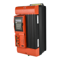
The switch disconnector of the device serves to interrupt the voltage supply of the
electronics cover. The feedback contact (NC contact) of the switch disconnector af-
fects the digital input DI08 of the device. If the device is connected to a DC 24 V
backup voltage, the status of the switch disconnector can be retrieved via digital input
DI08.
The switch disconnector can be secured with 3 locks.
32412133131
7.2 Binary controller
The behavior of the drive unit depends on the following factors:
• Selected configuration of the digital inputs.
• Status of digital inputs.
The following table describes the control functions in conjunction with the predefined
configurations of the digital inputs.
25891936/EN – 05/2020

 Loading...