5
Electrical installation
Connection diagram
Operating Instructions – MOVIMOT
®
advanced
51
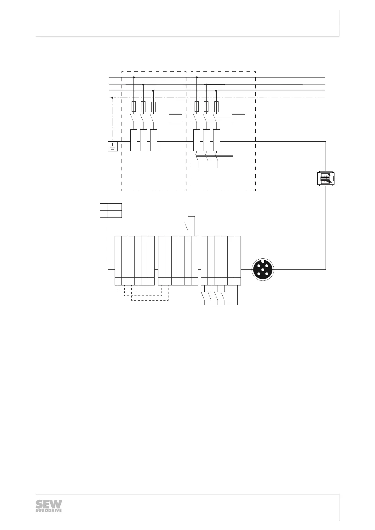
5.6 Connection diagram
L1
L2
L3
PE
K11
F11/F12/F13
L1
L2
L3
2 F_STO_P1
1 F_STO_P1
21 F_STO_P2
22 F_STO_P2
12 F_STO_M
11 F_STO_M
3 0V24_OUT
4 24V_OUT
23 0V24_IN
14 DOR-C
24 DOR-NO
25 0V24_OUT
26 24V_OUT
13 24V_IN
6 DI02
5 DI01
16 DI04
15 DI03
X1
X3
X9
X5231
X31
BW1
BW2
K11
F11/F12/F13
L1
L2
L3
X1a
MOVIMOT advanced
DRN..DBC
Line terminals
Braking resistor
Engineering interface
Control terminals
[1]
®
Analog input
Line terminals
Switch disconnector
[2]
[3]
32274774155
[1]
Jumpers installed at the factory for designs without plug connectors with STO
function. For additional information, refer to chapter "Functional safety".
[2]
Line terminals X1 only without switch disconnector
[3]
Line terminals X1a only with switch disconnector
For terminal assignment, refer to chapter "Terminal assignment".
For plug connector assignment, refer to chapter "Plug connectors".
5.6.1 Terminal functions in Easy mode (delivery state)
Positive direction of
rotation active (CW)
Negative direction of
rotation active
(CCW)
Setpoint f1 active Setpoint f2 active
25891936/EN – 05/2020

 Loading...