5
Electrical installation
Installation topology
Operating Instructions – MOVIMOT
®
advanced
46
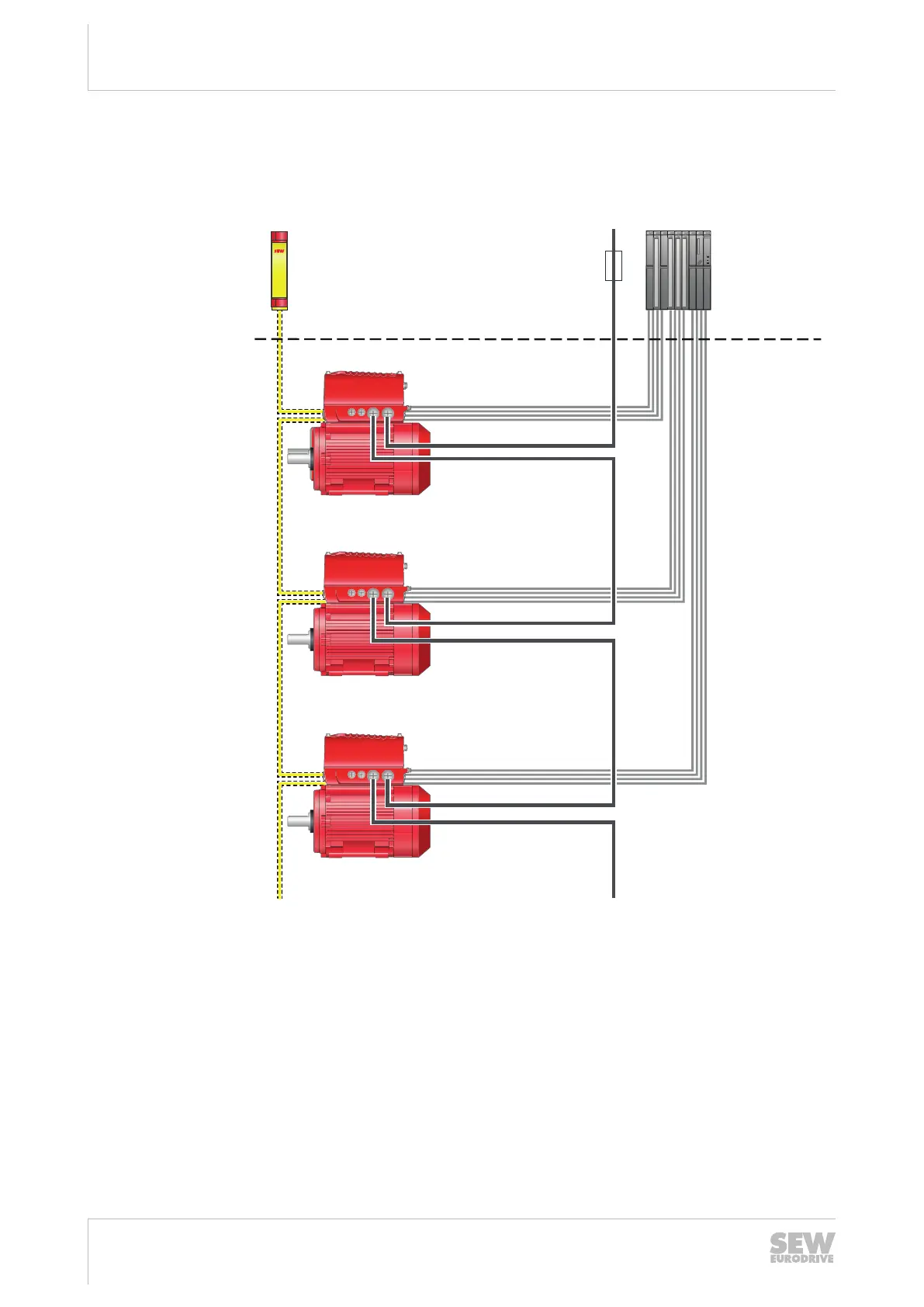
5.4 Installation topology
The following figure shows the basic installation topology with MOVIMOT
®
advanced:
MOVIMOT
®
advanced
MOVIMOT
®
advanced
MOVIMOT
®
advanced
Safety relay Supply system Control
Back-up
fuse/line
protection
Control cabinet level
Field level
Supply system
Binary control signals [2]
STO [1]
DBC..
DBC..
DBC..
32218059147
[1] The maximum permitted length of the STO cable between the safety relay and
the last drive unit is 100m.
[2] Control using up to 4 binary signals and 1 analog signal.
25891936/EN – 05/2020

 Loading...