3
Device structure
Electronics
Operating Instructions – MOVIMOT
®
advanced
22
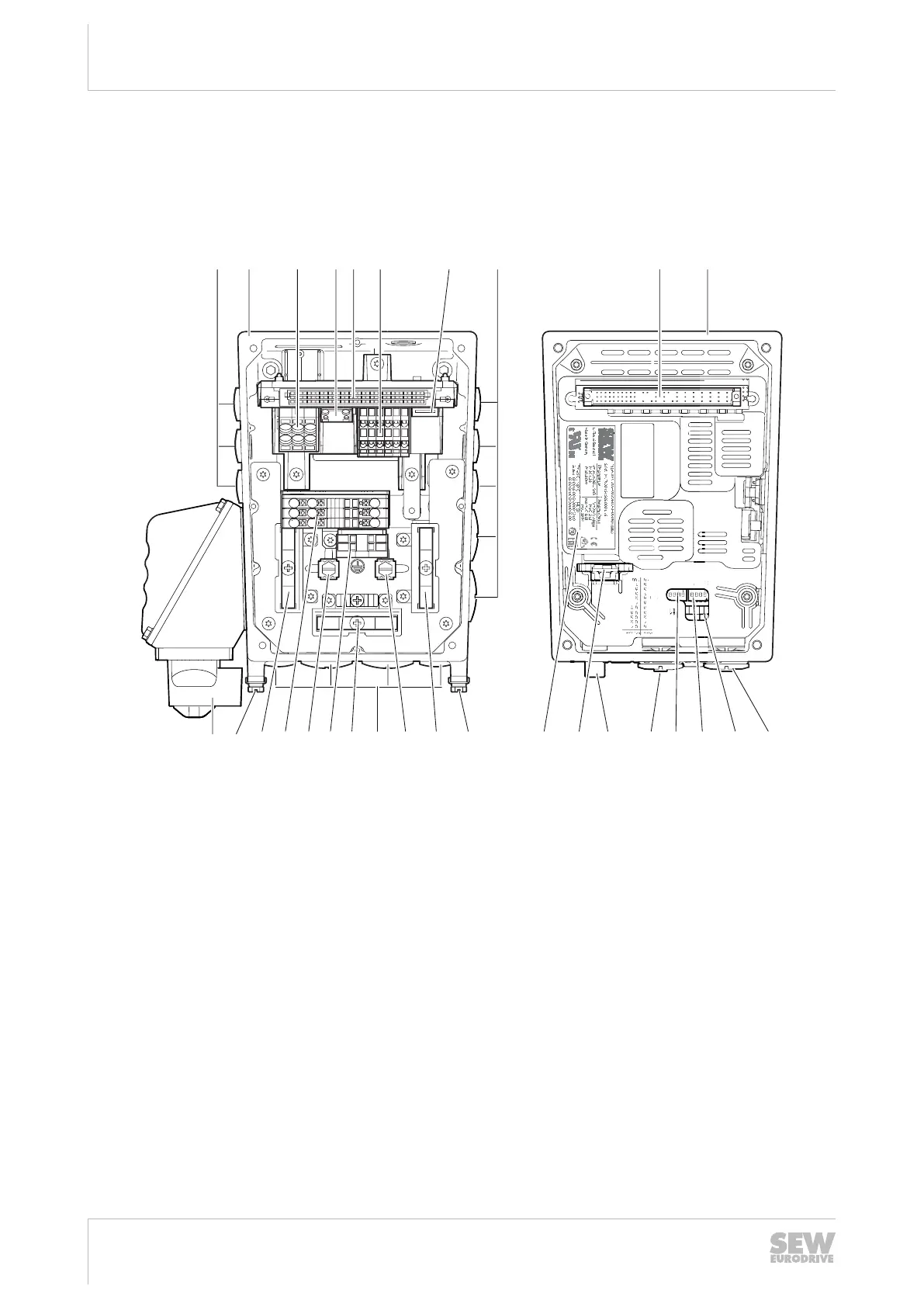
3.7 Electronics
3.7.1 Electronics cover (inside) and connection box
The following figure shows the connection box and the bottom side of the electronics
cover:
21
1
11
23
3
13
22
X1a
2
12
1B 2B
[20]
[1]
21
1
11
23
3
13
22
X1a
2
12
1B 2B
S1 1 2 3 4 1 2 3 4 S2
4321 4321
On
Off
f1 f2
ON
3
5
64
7
[5] [8]
[16] [11] [10][12][15] [14] [13] [9]
[2] [7][3] [5][4] [6] [1]
[17] [17][1] [17][17][21][19][18] [18] [18]
32211237899
[1] Cable glands
[2] Connection box
[3] Line connection L1, L2, L3 (X1, only WITHOUT switch disconnector)
[4] Braking resistor connection
[5] Plug connector connection unit for electronics cover
[6] Electronics terminal strip
[7] Engineering interface
[8] Electronics cover
[9] Potentiometer f1 (underneath the screw plug)
[10] Potentiometer t1
[11] DIP switches S1/1–S1/4
[12] DIP switches S2/1– S2/4
[13] Potentiometer f2 (underneath the screw plug)
[14] Plug connectors
[15] Replaceable memory module
[16] Electronics cover nameplate
[17] Screws for PE connection
[18] Shield clamps
[19] Line connection L1, L2, L3 (X1a, only in combination WITH switch disconnector)
[20] Switch disconnector (optional)
[21] Internal clamp connection
25891936/EN – 05/2020

 Loading...