5
Electrical installation
Terminal assignment
Operating Instructions – MOVIMOT
®
advanced
49
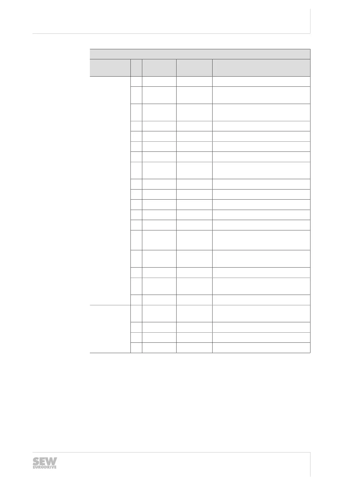
Assignment
Terminal No
.
Name Marking Function
X9
control termi-
nals
1 F_STO_P1 Yellow Input STO+
2 F_STO_P1 Yellow Input STO+
(to loop through)
3 0V24_OUT – 0V24 reference potential
for DC24V output
4 24V_OUT – DC24V output
5 DI01 – Digital input DI01
6 DI02 – Digital input DI02
11 F_STO_M Yellow Input STO_ground
12 F_STO_M Yellow Input STO_ground
(to loop through)
13 24V_IN – DC24V supply
14 DOR-C – Relay output DOR, common contact
15 DI03 – Digital input DI03
16 DI04 – Digital input DI04
21 F_STO_P2 Yellow Input STO+
22 F_STO_P2 Yellow Input STO+
(to loop through)
23 0V24_IN – 0V24 reference potential
for DC24V supply
24 DOR-NO – Relay output DOR, NO contact
25 0V24_OUT – 0V24 reference potential
for DC24V output
26 24V_OUT – DC24V output
X31
engineering
interface
1 0V24_OUT – 0V24 reference potential
for DC24V auxiliary output
2 CAN_L – CAN Low connection
3 CAN_H – CAN High connection
4 24V_OUT – DC24V auxiliary output
1) With the switch disconnector option, the line terminal X1 is assigned to the internal wiring.
25891936/EN – 05/2020

 Loading...