5
Electrical installation
Connection diagram
Operating Instructions – MOVIMOT
®
flexible
68
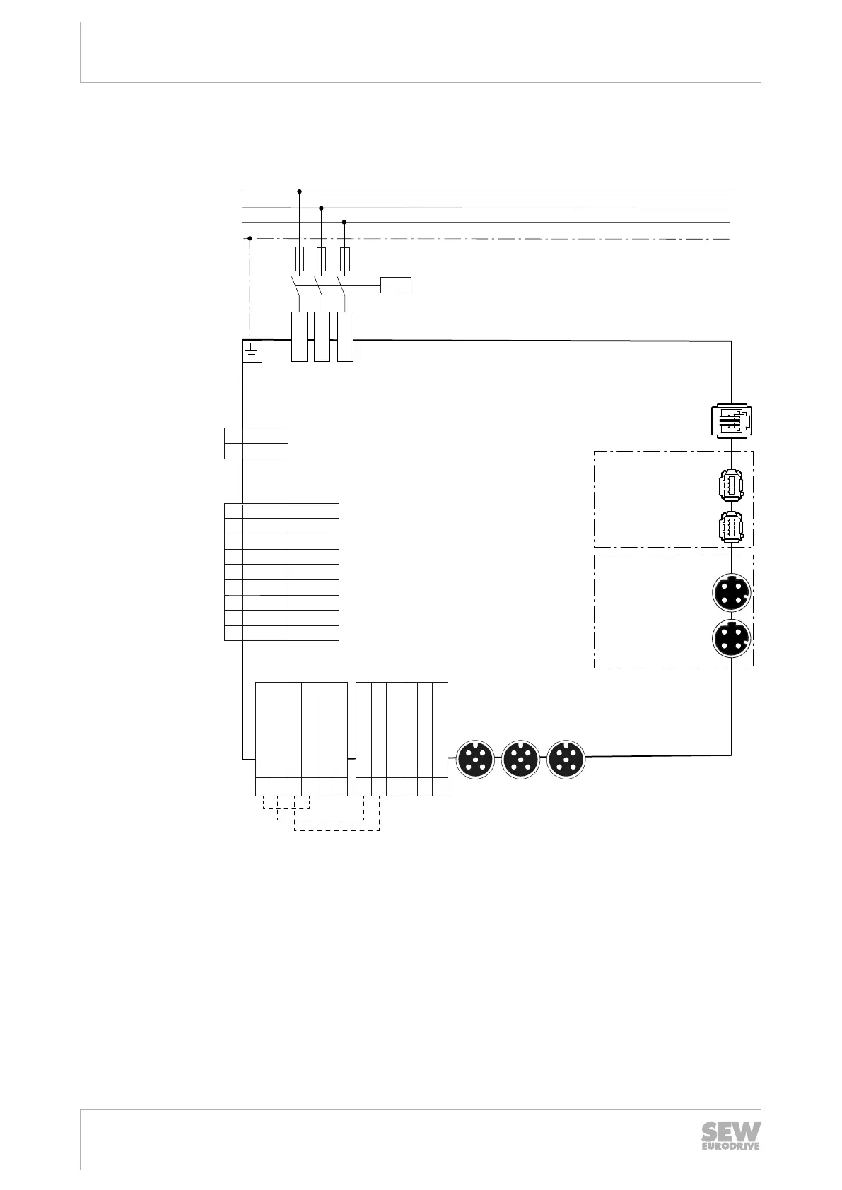
5.7 Connection diagram
The following figure shows the connections of the device:
L1
L2
L3
PE
K11
F11/F12/F13
L1
L2
L3
2 F_STO_P1
1 F_STO_P1
21 F_STO_P2
22 F_STO_P2
12 F_STO_M
11 F_STO_M
3 0V24_out
4 24V_out
23 0V24_in
14 24V_in
24 0V24_in
13 24V_in
X5133_1
X5133_2
X5133_3
1 BW
BW2
A1
/CO [4]
B B
A
–
C C
D D
U U
V V
W
T2
W
Temp-
/DI [4]
Temp+
14
13
15
U
V
W
X1 line terminals
X3 braking resistor
X2_A Terminals for motor,
brake and temperature sensor
EtherCAT®/
X9 control terminals
Digital inputs/outputs
X31 engineering interface
[1]
[2]
[3]
PE
Mini IO
M12
MOVIMOT® flexible MMF1..-C/DSI.., MMF3..-C/DSI..
SBus
PLUS
PLUS
SBus
EtherCAT®/
IN X42
OUT X43
IN X4233_1
OUT X4233_2
29289146635
[1] Only for designs with electronics cover DSI.1.. (in preparation)
[2] Only for designs with electronics cover DSI.0..
[3] Jumpers installed at the factory for designs without plug connectors with STO
function. For additional information, refer to chapter "Functional safety".
[4] Connection unit option, see chapter "Type designation connection unit"
For terminal assignment, refer to chapter "Terminal assignment".
For plug connector assignment, refer to chapter "Plug connectors".
29128668/EN – 12/2019
 Loading...


