5
Electrical installation
Installation topology (example: standard installation)
Operating Instructions – MOVIMOT
®
flexible
57
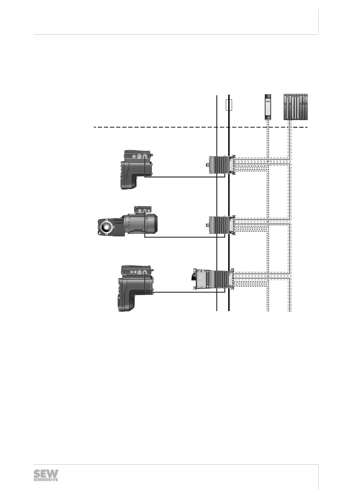
5.4 Installation topology (example: standard installation)
The following figure shows a basic installation topology with the device:
Safety
relay
24 V
backup mode
Supply system
Control
Back-up
fuse/line
protection
Control cabinet level
Field level
[5] Fieldbus
[4] STO
[3] 24V
[2] MMF1../DSI.0..
[2] MMF1../DSI.0..
[2] MMF3../DSI.0..
[1] MGF..-DSM-C
[1] ..DRN...
[1] MGF..-DSM-C
29493378827
[1] Connected drive units with/without digital interface
[2] MOVIMOT
®
flexible with DSI.0.. electronics cover with 2×M12 fieldbus connec-
tion
[3] The decentralized frequency inverter is equipped with an integrated DC24V
supply. As an option, the electronics of the decentralized frequency inverter may
be supported by an external DC24V supply.
[4] The STO cable between the safety relay and the last decentralized frequency in-
verter may not be longer than100m.
[5] The maximum permitted cable length of the Ethernet fieldbus cable between the
decentralized inverters is 100m. The maximum permitted cable length between
controller and decentralized frequency inverter is 100m. The permitted length
may be reduced due to technical data of the controller.
29128668/EN – 12/2019
 Loading...


