10
UK
DEFINITION OF WARNING SIGNS
Warning indication of a risk for the machine or its
operator.
Warning indication of the presence of a risk of
electrical origin
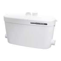
1. APPLICATION
SANICOM® is a lifting pump for wasterwater originating from sinks, clothes
washing machines, dishwashers, showers or baths and basins, used in private
or commercial applications (restaurants, hairdressings salons,...).
The unit has a high performance level, and is safe and reliable, provided all
the rules for installation and maintenance in this notice are strictly followed
3. INSTALLATION
The SANICOM® installation must comply with EN12056-4 standards. All work
to install the equipment, put it into service and carry out maintenance must
be done by a qualied professional specialist.
3.1 FITTING
• The space in which SANICOM® is installed must be large enough to leave at
least 600mm around the unit for easy maintenance. This space must be well
lit, ventilated, and must never be immersed in water and must be protected
from frost.
• Isolation valves should be tted to the inlet pipework and discharge
pipework to isolate the unit in case of the need for service.
• This discharge pipe must be designed so as to prevent back-ow from the
sewers. Backow is avoided by installing an anti-backow loop located
above the back-ow level..
COMMENT : UNLESS OTHERWISE STATED LOCALLY, THE BACKFLOW
LEVEL CORRESPONDS TO THE LEVEL OF THE ROAD OR PAVEMENTS,...
• The pumping station must always be ventilated so that the tank is always
at atmospheric pressure. The ventilation must be completely free and air
must ow in both directions (no diaphragm valve tted). Do not connect to
a mechanically controlled ventilator.
3.2 ELECTRICAL CONNECTION
Do not make the electrical connection until the nal connections are
completed
4. COMMISSIONING
Once the plumbing and electrical connections have been made, check that
the connections are watertight by letting water ow successively through
each inlet used. Make sure that the unit is operating correctly by carrying out
at least two start cycles with water to test the system.
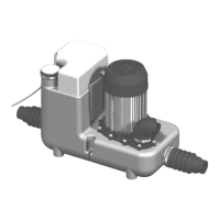
2. DESCRIPTION
2.1 OPERATING PRINCIPLE
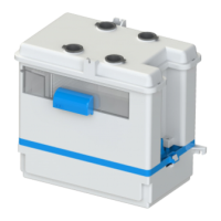
SANICOM® 1 contains 1 pump.
The tank is equipped with 2 tubes, one controls motor activation, and the
second controls the alarm system.
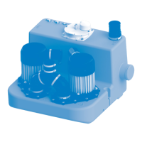
SANICOM® 2 contains two independent pumps. Both pumps operate
alternately to ensure even ware. In case of surcharge operation, both motors
run simultaneously (or if one pump fails, the other takes over).
The tank is equipped with three dip tubes, two of which control motor
activation, and the third controls the alarm system.
2.2 TECHNICAL DATA
SANICOM® 1 SANICOM® 2
Type P 95 R 90
Maximum vertical pumping height 8 M 10 M
Voltage 220-240 V 220-240 V
Frequency 50-60 Hz 50-60 Hz
Maximum power consumption 750 W 3 000 W
Maximum current consumption 3.3 A 13 A
Electrical class I I
Protection index IP X4 IP X4
Max temp with intermittent functioning 90°C 90°C
Net weight 10 kg 26 kg
5. USE
SANICOM® is designed for disposing of greywater originating from sinks,
clothes washing machines, dishwashers, showers or baths and basins.
SANICOM® can pump out hot water.
Do not dispose of concentrated chemical products (acids, solvents, bases,
oxidants, reducers, etc.) into sanitary ware connected to the SANICOM®.
In the event of power failure, stop all water flow to the
appliances connected to the SANICOM®.
In case of discharge of greasy euents, the use of a degreasing tank is
essential.
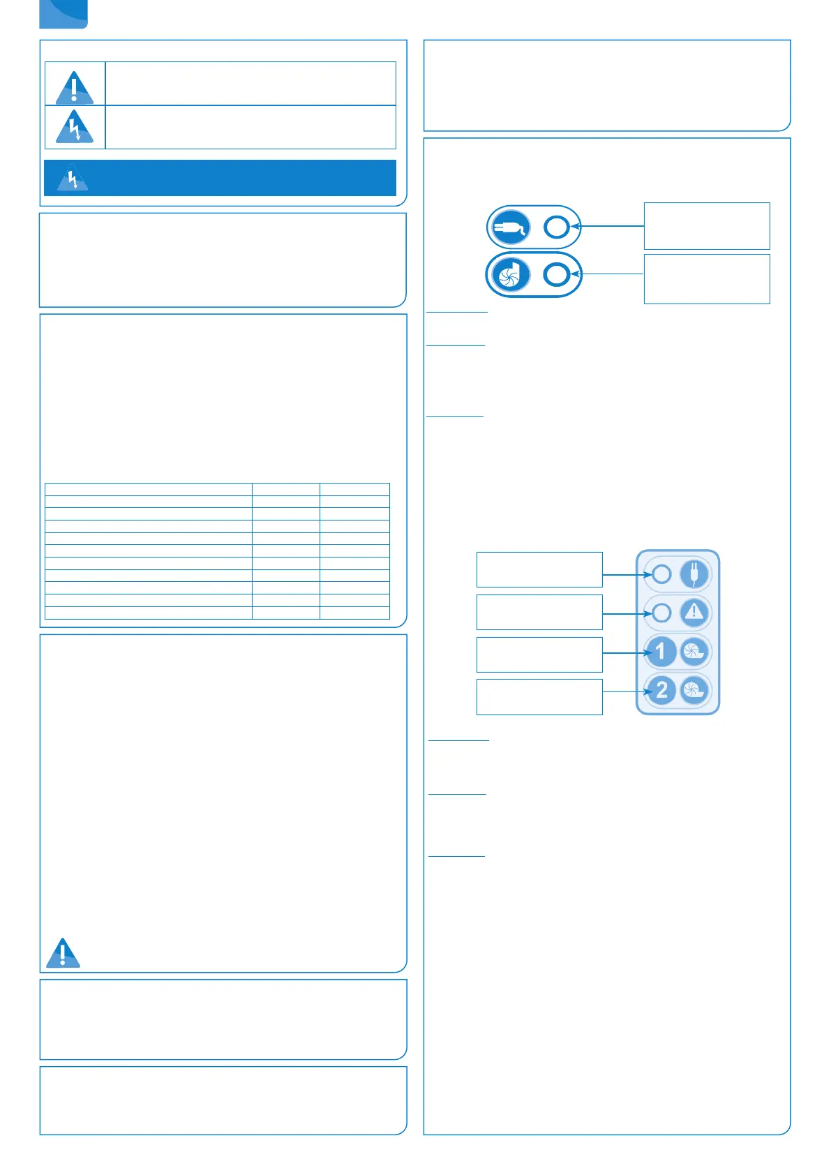
LED:
- Green: Power on
- Red: Alarm
BUTTON:
Manual motor activation
Alarm reset
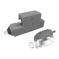
6. CONTROL BOX OPERATION
6.1 SANICOM 1: CONTROL KEYPAD OPERATION
1/ General alarms
Mains alarm :
If the LED is off, there is no power supply.
Level alarm :
If the water level inside the device is abnormally high, the high level diptube
microswitch will activate the motor and the alarm LED lights up red. If this
LED flashes red, it indicates a detection problem for the normal water level
(Long dip tube).
Time alarm :
If the motor runs continuously for more than 1 minute, the red LED alarm
lights up.
2/ Reset alarm
The button on the keypad will only allow you to turn off the red LED (it will
turn green) if the problem that triggered the alarm has been resolved.
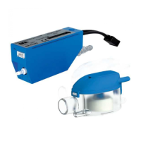
6.2 SANICOM 2 : REMOTE CONTROL BOX OPERATION
1/ General alarms
Mains alarm :
In case of power failure (or when unplugging the device): the buzzer is
triggered + the red alarm LED lights up + the yellow mains LED flashes.
Level alarm :
If the water level inside the device is abnormally high: the buzzer is triggered
+ the red alarm LED lights up + both motors start-up. If this LED flashes red,
it indicates a detection problem for the normal water level (Long dip tube).
Time alarm :
If one of the two motors runs for more than 1 minute: the buzzer is triggered
+ the red alarm LED lights up + the other motor starts-up.
2/ General alarm reset
If the problem that triggered an alarm above disappears, the buzzer stops, but
the red alarm LED remains on until the next normal cycle.
One of the two keypad keys will stop the buzzer in any cases, but it will only
turn o the red LED if the problem that caused the alarm has been resolved.
The alarms of the remote box also remain active until the problem has been
solved. This prevents the system from being «abandoned» in default.
NOTE : Option of connection to an external alarm (SANICOM®2).
Option of externalising the alarm signal. Dry contact (no voltage) NO (normally
open) operated by a relay.
Yellow LED:
mains supply
Red LED:
alarm
Manual activation:
Motor 1
Manual activation:
Motor 2
DISCONNECT THE STATION BEFORE ANY
INTERVENTION !
 Loading...