SHARP(CHINA)INVESTMENT CO.,LTD
Main cause Inspection method Normal value/condition Remedy
Remote control not designed to allow
fan speed change.
Check operation mode.
Fan speed should change ex-
cept during dehumidifying ope-
ration, sleep operation,internally
normal operation
Explain to user.
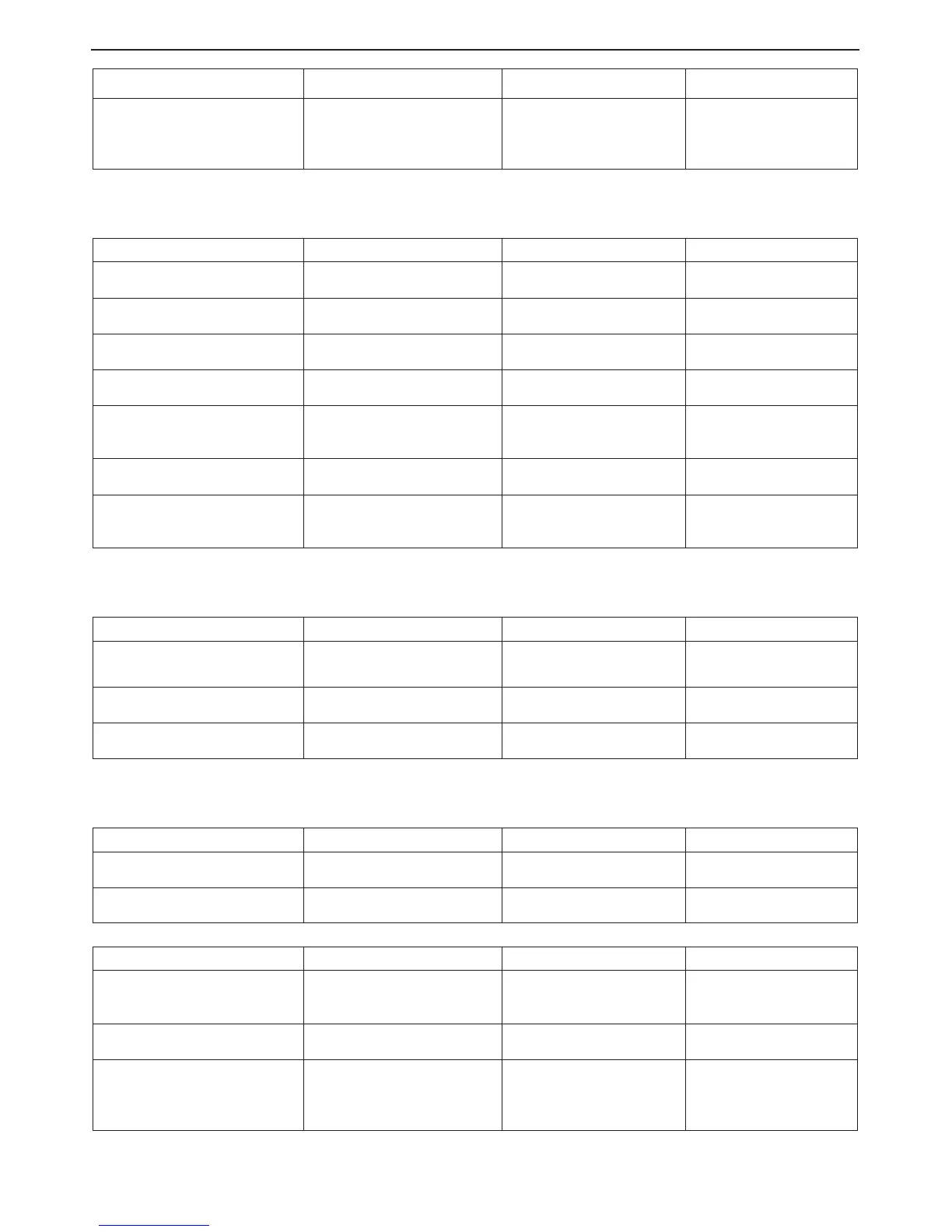
4. Remote control signal is not received
Main cause Inspection method Normal value/condition Remedy
Batteries at end of service life. Measure battery voltage.
2.5 V or higher (two batteries in
series connection)
Install new batteries.
Batteries installed incorrectly. Check battery direction.
As indicated on battery
compartment.
Install batteries in indicated
direction.
Lighting fixture is too close, or
fluorescent lamp is burning out.
Turn off light and check. Signal should be received when
light is turned off.
Change light position or install
new fluorescent lamp.
Operating position/angle is
inap-propriate.
Operate within range specified in
manual.
Signal should be received within
range specified in manual.
Explain appropriate handling
to user.
Open-circuit or short-circuit in wiring
of light receiving section.
Check if wires of light receiving
section are caught.
Wires of light receiving section
should not have any damage
caused by pinching.
Replace wires of light
receiving section.
Defective light receiving unit.
Check signal receiving circuit Tester indicator should move
when signal is received.
Replace PCB.
Dew condensation on light receiving
unit.
Check for water and rust. Signal should be received within
range specified in manual.
Take moisture-proof measure
for lead wire outlet of light
receiving section.
5. Vane do not move
Main cause Inspection method Normal value/condition Remedy
Caught in sliding section. Operate to see if vane are caught
in place.
Vane should operate smoothly.
Remove or correct catching
section.
Disconnected connector (CN5 on
relay PCB, louver motor side)
Inspect connectors. Connectors or pins should not
be disconnected.
Install correctly.
Contact of solder on PCB(connector
section on PCB)
Check visually. There should not be solder
contact.
Correct contacting section.
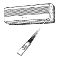
6. Compressor does not start
Main cause Inspection method Normal value/condition Remedy
Erroneous inter-unit connection. Check wiring between indoor and
outdoor units.
Terminal board 1-N: 230 VAC,
50 Hz
Correct wiring.
DamageD IPM Check IPM continuity Replace IPM
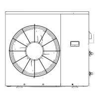
Main cause Inspection method Normal value/condition Remedy
Blown outdoor unit fuse. Check 20-A fuse.Check 15-A fuse. Fuse should not be blown. Replace fuse.
Replace outdoor unit PWB
assembly.
Power supply voltage is too low. Measure power supply voltage
during startup.
220± 10 VAC, 50 Hz Make sure that power supply
voltage is 198 V or higher.
Compressor lock. Supply current and touch com-
pressor cover (sound absorbing
material) to check if operation
starts.
Compressor should start nor-
mally.
Apply external impact to
compressor.Replace
compressor.
3-7