Do you have a question about the Sharp AL-1540CS and is the answer not in the manual?
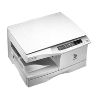
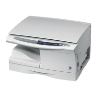
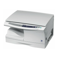
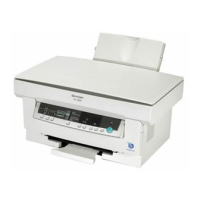
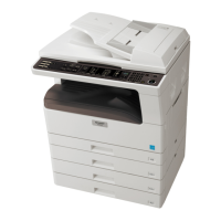
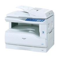
Lists the main functions and configurations of the copier models.
Details the fundamental physical and dimensional specifications of the copier.
Outlines operational parameters like paper feed systems, sizes, weights, and original handling.
Details copy speeds, magnification ratios, and copy quality parameters.
Lists specifications for the GDI printer function, including print speed and resolution.
Outlines scanner specifications like resolution, scan speed, and supported OS.
Details specifications for the Single Path Feeder (SPF), including capacity and original size.
Specifies requirements for the Reversible Single Path Feeder (RSPF), including capacity and speeds.
Lists consumable parts including develop cartridges and drum cartridges with their content and life.
Details normal, acceptable, and storage environmental conditions for optimal machine operation.
Explains how to identify production control numbers on developing and drum cartridges.
Provides visual identification of external components of the copier.
Identifies key internal components and their locations within the copier.
Details the function and indicators of the copier's operation panel.
Lists and describes the function of various motors and solenoids used in the copier.
Identifies and explains the function of sensors and switches within the copier.
Lists and describes the functions of the various Printed Wiring Board (PWB) units.
Provides a cross-sectional diagram of the copier, illustrating internal mechanisms and parts.
Guides on proper installation to prevent damage and ensure optimal performance.
Provides essential handling precautions to maintain copier performance and safety.
Guides users to verify that all included components and accessories are present.
Instructs on the proper procedure for unpacking the copier for installation.
Details steps for removing protective tapes and covers before installation.
Provides step-by-step instructions for installing the Toner Developer (TD) cartridge.
Guides on how to properly load copy paper into the paper trays.
Explains how to connect the power cord and turn on the copier for the first time.
Details the software included on the CD-ROM for printer, scanner, and utility functions.
Explains how to connect USB and parallel interface cables for computer communication.
Details the specifications and pin configuration for the parallel interface connection.
Describes the connector and cable specifications for the USB interface.
Provides instructions for safely moving the copier unit.
Illustrates the basic operational cycle of the copying process.
Explains the non-impact printing process using a semiconductor laser and OPC drum.
Details the step-by-step process of image formation, transfer, and fusing during printing.
Describes the overall operational flow, including image scanning, processing, and printing.
Describes the scanner unit, its optical system, and drive system for image scanning.
Explains the laser unit's structure, beam path, and composition for writing images.
Details the fuser section's components and thermal control for fusing toner onto paper.
Explains paper feeding methods and the transport path for smooth paper movement.
Describes the mechanism that detects the installation of a new drum unit.
Outlines the Single Path Feeder (SPF) installation and its document transport path.
Explains the paper and document transport process for duplex copying modes.
Details the procedure for disassembling and assembling the high voltage section.
Provides steps for disassembling and assembling the operation panel unit.
Details the disassembly and assembly procedures for the copier's optical section.
Guides on disassembling and assembling the fusing unit components.
Provides steps for disassembling and assembling the tray paper feed and transport mechanisms.
Details the disassembly and assembly procedures for the manual paper feed section.
Guides on disassembling and assembling the rear frame components of the copier.
Details the disassembly and assembly of the power supply unit.
Explains disassembly and assembly for the SPF unit, including sensor PWB and pickup solenoid.
Provides steps for removing and installing the second cassette paper feed unit.
Guides on disassembling the duplex motor section, including rear cabinet and main PWB removal.
Details disassembly and assembly of the reverse roller unit.
Covers disassembly of the RSPF, including intermediate tray and pickup unit removal.
Covers adjustments for copy magnification ratio and image position for optical performance.
Adjusts various image position parameters for optimal placement on the paper.
Adjusts the lead edge position and image loss amount for accurate print alignment.
Adjusts the void amount at the image rear edge to prevent paper jams.
Adjusts the copy image position to align the center line accurately on the paper.
Adjusts copy density levels for different modes to achieve desired print quality.
Details procedures for adjusting main charger (grid bias) and DV bias for proper operation.
Adjusts paper reverse position and trailing edge void for duplex copying.
Explains the procedure to enter the serviceman simulation mode for diagnostics and settings.
Provides a comprehensive list of available simulation codes and their functions.
Explains the operation and procedure for various simulation codes, including sensor status and motor checks.
Lists and details various trouble codes, their causes, and cancellation methods.
Lists functions like auto clear, pre-heat, and auto shut off that can be configured by the user.
Guides on how to change settings for user programs like auto clear time and pre-heat duration.
Describes how to adjust AE level for OC and SPF modes for optimal copy density.
Explains how to enable or disable the toner save mode for reduced toner consumption.
Presents the overall block diagram of the copier's electrical system, showing major components and their connections.
Details the MCU PWB, including its components and connections.
Provides detailed circuit descriptions for various sections like Main PWB and ASIC.
Describes the MCU PWB, its CPU signal table, and circuit functions.
Lists signals and their connections for the ASIC, crucial for image processing.
Details the Image process ASIC, including its sections and functions.
Explains the reset circuit that controls start/stop based on power status.
Details the heater lamp control circuit, including temperature monitoring and protection.
Describes the solenoid driver circuit that uses a Darlington circuit for load driving.
Explains the drive circuit for the toner supply motor, controlled by ASIC pulse signals.
Details the drive circuit for the main motor, controlled by MMD signals from ASIC.
Explains control circuits for stepping motors, including mirror and duplex motors.
Covers the operation circuit, composed of key matrix and display matrix circuits.
Details the interface circuit, including USB and IEEE1284 drivers for communication.
Describes the carriage unit containing CCD PWB, inverter PWB, and lamps for scanning.
Explains the DC power circuit, including AC rectification, switching conversion, and voltage regulation.
Describes the noise filter circuit composed of L and C components to reduce common and normal mode noises.
Explains the rush current prevention resistor and the circuit for rectifying and smoothing AC voltage.
Details the flyback converter system used as a DC-DC converter for power supply.
Explains the overcurrent protection circuit that shuts off power when excessive current occurs.
Describes the circuit for rectifying and smoothing the high frequency pulse from the inverter to +5V.
Displays the circuit diagram for the MCU PWB, focusing on the CPU section.
Provides the circuit diagram for the MCU PWB, focusing on the ASIC section.
Displays the circuit diagram for the MCU PWB, specifically for the memory section.
Shows the circuit diagram for the MCU PWB, covering driver sections.
Presents the circuit diagram for the MCU PWB, illustrating driver sections.
Displays the circuit diagram for the MCU PWB, focusing on driver sections.
Shows the circuit diagram for the MCU PWB, detailing noise filter and pull-up sections.
Illustrates the circuit diagram for the MCU PWB, focusing on connector sections.
Provides the circuit diagram for the MCU PWB, detailing connector sections.
Displays the circuit diagram for the power supply unit (120V/127V).
Presents the actual wiring diagram for various units of the copier.