10
Terminals
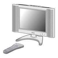
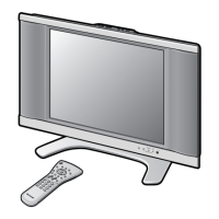
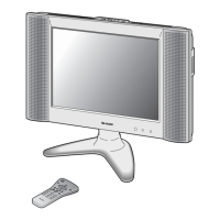
Part Names – Main Unit
S-VIDEO
VIDEO
AUDIO (L)
AUDIO (R)
AV-IN2 (AV)
(21pin Euro-SCART)
AV-IN1 (RGB)
(21pin Euro-SCART)
AUDIO OUT (DIGITAL)
POWER INPUT
DC13V
OUT
IN
ANTENNA
(DIGITAL
TUNER)
RS-232C*
terminal
C.I.
(Common
Interface)
See page 32.
ANTENNA INPUT
(ANALOG TUNER)
EXTERNAL
SPEAKER (4Ω 5W)
How to fix the cables
• Secure cables and cords with the supplied
cable clamps so that they do not get caught
when mounting the cover.
Cable clamps
AV-IN3
* Terminal for expanded
functionality in the near
future.
• Use the opening under the centre terminal cover to
guide cables to the right side.
Cautions when bundling the cables
■ If you connect cables to every rear terminal on the left side, bundle the AV, S-Video and optical fibre cables
along with the AC cord together and guide them through the opening on the right side terminal cover.
For the two SCART cables, guide them through the opening on the left side terminal cover.
How to bundle and guide the cables through the opening to the right side:
■ The same as connecting the antenna cable. Guide the bundled cables under the centre terminal cover so they
come out of the opening on the right side.
lc22ad1e_en_p01_12 04.2.2, 11:06 AM10