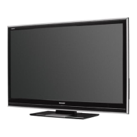
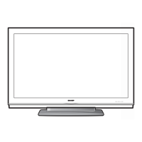
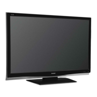
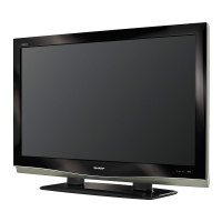
Part Names
* OPC: Optical Picture Control
*2
[ Remote control sensor h
L L °Fic P°i_ _ilWleRi_c(aiii(PSig_p2a1i)e14.)l
h .___ ._______. oPo indicator (See page 21 .) J
ER
POWER
button
_u MENU
button
_T iNPUT
button
CH
__ Channel
buttons
(CHA/V)
+ Volume
buttons
(VOL + / - )
INPUT 5
- terminal
........... (HDMI)
®
VIDEO
®_ INPUTS
AUDIO - terminals
®,
IIill SERV,CE
= terminal
AC INPUT
terminal
INPUT 7 terminal
(HDMI)
INPUT 9 terminal
(HDMI)
INPUT 8 terminal
(HDMI)
DIGITAL AUDIO
OUTPUT terminal
AUDIO OUTPUT
terminals
_ Antenna!Cable in
INPUT 1 terminals
INPUT 2 terminals
RS-232C terminal
INPUT 4 terminal (PC-IN)
(shared for INPUT 4 and INPUT 6) *4
6 terminal (HDMI)
d
"1 See pages 12 and 13 for external equipment connection.
*2 See page 20 for button operations.
*3 See page 7 for connecting the AC cord.
*4 See page 28 for details on the PC Audio Select function.
• The illustrations in this operation manual are for explanation purposes and may vary slightly from the actual operations.
Q-10