– 15 –
CD-BP2000W/210W/2000A/BK2000W/210W
CD SECTION
• AM IF/RF
Signal generator: 400 Hz, 30%, AM modulated
*1. Input: Antenna, Output: TP302
*2. Input: Antenna, Output: TP301
TUNER SECTION
fL: Low-range frequency
fH: High-range frequency
AM IF 450 kHz 1,602 kHz T351 *1
AM Band — 531 kHz (fL): T306 *2
Coverage 1.1 ± 0.1 V
AM Tracking 990 kHz 990 kHz (fL): T303 *1
*1. Input: Antenna, Output: TP301
*2. Input: Antenna, Output: Speaker terminal
• FM RF
Signal generator: 1 kHz, 40 kHz dev., FM modulated
FM Band — 87.50 MHz T301(fL);
*
1
Coverage
1.3 V ± 50 mV
FM RF 98.00 MHz 98.00 MHz L312 *2
(10-30 dB)
Test Stage
Instrument
Connection
Frequency
Frequency
Display
Serring/
Adjusting
Point
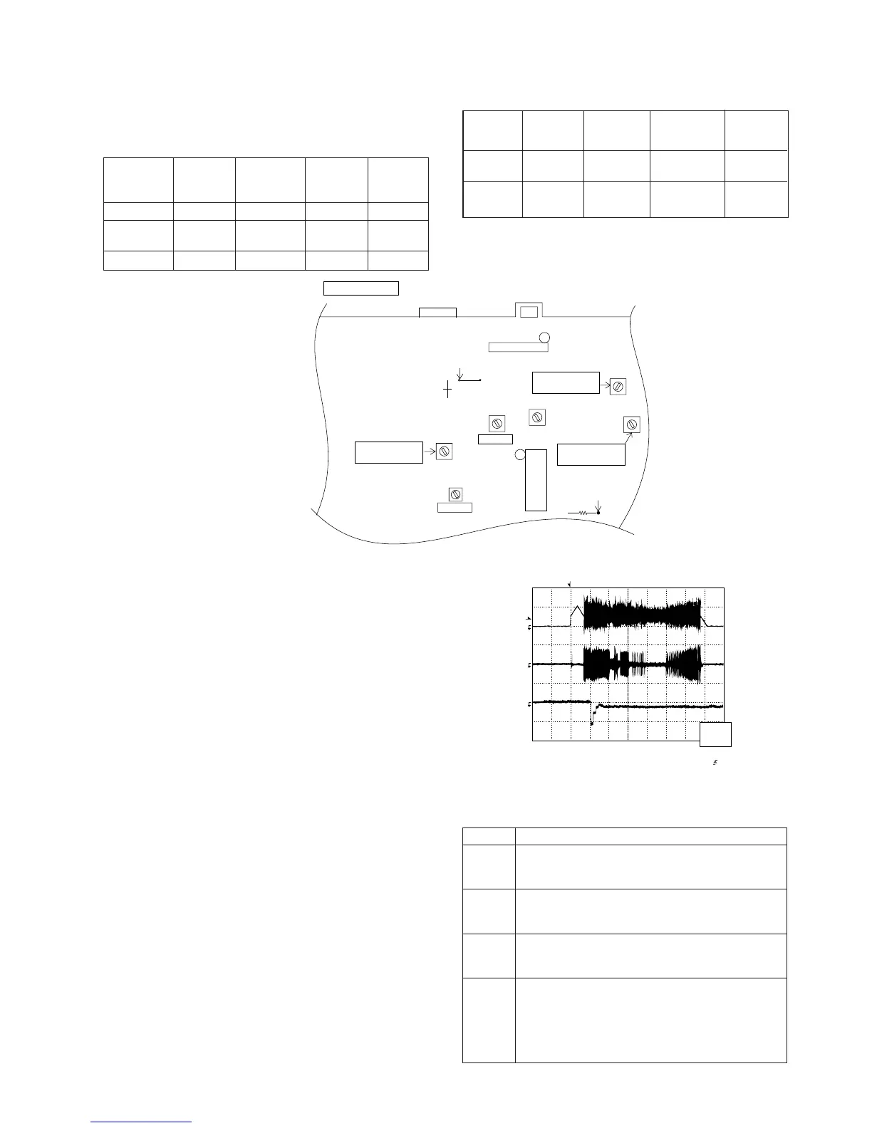
Figure 15-1 ADJUSTMENT POINT
Test Stage Frequency
Frequency
Display
Setting/
Adjusting
Parts
Instrument
Connection
IC301
IC303
R381
TP302
TP301
R357
AM IF
FM IF
T303
T306
AM
TRACKING fL
AM BAND
COVERAGE fL
FM BAND
COVERAGE fL
T351
MAIN PWB
CNP302
AM LOOP
ANTENNA
T301
T302
L312
SO302
FM ANTENNA
1
1
Figure 15-2
CD ERROR CODE DESCRIPTION
Error State Code
[Servo System Error]
0001 Cannot detect Pickup-in SW
0002 DSP access error
[Error during close operation]
0101 Open/Close SW not functioning (Low → High)
0103 Open/Close SW not functioning (High → Low)
[Error during open operation]
0201 Open/Close SW not functioning (Low → High)
0203 Open/Close SW not functioning (High → Low)
[Error during skip operation]
0302 Pickup-in SW is not detected
0306 During Disc 1 search, Open/Close SW or Clamp SW
or Disc SW do not change to low.
0307 Clamp SW not function (Low → High)
0308 Clamp SW not function (High → Low)
Since this CD system incorporates the following automatic
adjustment functions, readjustment is not needed when
replacing the pickup. Therefore, different PWBs and pickups
can be combined freely.
Each time a disc is changed, these adjustments are
performed automatically. Therefore, playback of each disc
can be performed under optimum conditions.
Items adjusted automatically
(1) Offset adjustment (The offset voltage between the head
amplifier output and the VREF reference voltage is
compensated inside the IC.)
* Focus offset adjustment
* Tracking offset adjustment
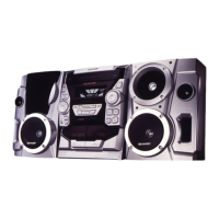
(2) Tracking balance adjustment (waveform drawing 15-2
EFBL)
(3) Gain adjustment (The gain is compensated inside the IC
so that the loop gain at the gain crossover frequency will
be 0dB.)
* Focus gain adjustment
* Tracking gain adjustment
Adjustment
T
T
EFBL
FDO
TE
Stopped
CH1=500mV
DC 10:1
CH2=200mV
DC 10:1
CH3=1V
DC 10:1
500ms/div
(500ms/div)
NORM:20kS/s
1
2
3
=Record Length=
Smoothing : ON CH1 : 0.000V
CH2 : 0.000V
Main : 100K
Zoom : 2k
Mode : SINGLE
Type : EDGE CH1
Delay : 0.0ns
Hold off : 0.2us
CH3 : 0.00V
CH4 : 0.00V
BW : FULL
=Trigger==Filter= =Offset=
CH2
v/DIV
200mV
1999/04/05 20:26:47