CD-BP2000W/210W/2000A/BK2000W/210W
– 48 –
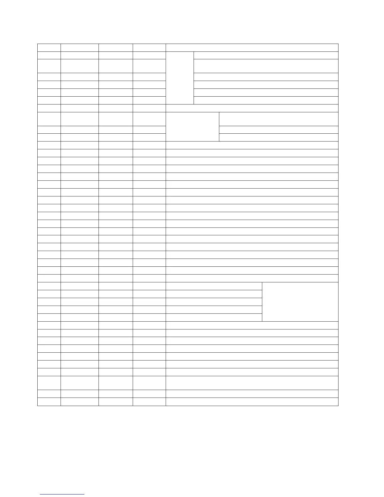
IC2 VHiLC78641E-1: Servo/Signal Control (LC78641E) (1/2)
1 PDO1 Output – For PULL Phase-comparison output terminal for built-in VOC control.
2 PDO2 Output – Phase-comparison output terminal for built-in VOC control.
Rough servo : OFF, phase servo : ON.
3 VVSS – – Ground terminal for built-in VCO.
4 PCKIST AI – Resistor terminal for setting the PDO output current.
5 VVDD – – Power terminal for built-in VCO.
6 FR AI – Resistor terminal for setting the VCO frequency range.
7 HFL Input – Mirror detection signal input terminal.
8 SLCIST AI – For slice level control
Resistance connection terminal for current adjustment of
SLCO output.
9 SLCO Output – Control output.
10 EFMIN Input – EFM signal input terminal.
11* JITTV Output Unfixed Jitter detection/monitor terminal.
12 JITTC Output – Jitter detection/adjustment terminal.
13 BH Input – BH signal input terminal. A/D input.
14 PH(RFENV) Input – PH signal or RFENV signal input terminal. A/D input.
15 FE Input – FE signal input terminal. A/D input.
16 TE Input – TE signal input terminal. A/D input.
17 VREF Input – VREF signal input terminal. A/D input.
18 ADAVDD – – AD for servo, D/A power terminal.
19 ADAVSS – – AD for servo, D/A ground terminal.
20* PHREF Output (1/2VDD) PH reference output terminal. D/A output.
21* BHREF Output (1/2VDD) BH reference output terminal. D/A output.
22 TBLO Output (1/2VDD) Output terminal for tracking balance. D/A output.
23 TDO Output (1/2VDD) Output terminal for tracking control. D/A output.
24 FDO Output (1/2VDD) Output terminal for focus control. D/A output.
25 SPDO Output (1/2VDD) Output terminal for spindle control. D/A output.
26 SLDO Output (1/2VDD) Output terminal for sled control. D/A output.
27* FG Input – FG signal input terminal. (When not used,connect to 0V)
28 LASER Output L LASER ON/OFF control terminal.
29 CONT1 In/Output Input mode General purpose input/output terminal 1.
Controlled with serial data command
30 CONT2 In/Output Input mode General purpose input/output terminal 2.
from microcomputer
.
When not used,
31 CONT3 In/Output Input mode General purpose input/output terminal 3.
set it as the input terminal
and
32 CONT4 In/Output Input mode General purpose input/output terminal 4.
open it by connecting
to 0V, or set it
33 CONT5 In/Output Input mode General purpose input/output terminal 5.
as the output terminal and open it.
34* PCK Output H Clock monitor terminal for EFM data replay. 4.3218MHz as phase clock.
35* C2F Output H C2 flag output terminal.
36 VDD – – Power terminal of digital system.
37* DOUT Output L Output terminal of digital OUT. (EIAJ format)
38* FSX Output L
Output terminal of synchronous signal of 7.35kHz divided from quartz oscillation.
39* EFLG Output L C1,C2 correct monitor terminal.
40 TEST Input – Input terminal for test. Surely connected to 0V.
41* EMPH In/Output Input mode
Emphasis terminal. After resetting, it is configured as an input terminal. It can be controlled
from the outside. It is also becomes a emphasis monitor terminal under command control.
42* MUTEL Output H Mute output terminal for L channel.
43* MUTER Output H Mute output terminal for R channel.
Pin No.
Function
Terminal Name
Input/Output
Setting in Reset
In this unit, the terminal with asterisk mark (*) is (open) terminal which is not connected to the outside.