– 17 –
CD-CH1000
143 144
141
133
132
147
146
128
110
Mark position
111
145
142
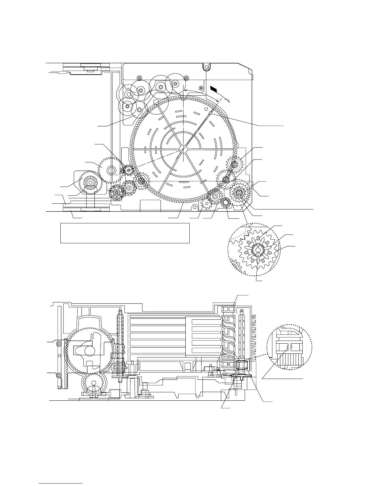
LIFT GEAR A
130
TRAY DRIVE GEAR F
135
TRAY JOINT GEAR F
135
TRAY JOINT GEAR F
102
CHANGE BOX L
*1
130
TRAY DRIVE GEAR F
140
LIFT CAM
140
LIFT CAM
130
TRAY DRIVE GEAR F
135
TRAY JOINT GEAR F
37°
*2
TRAY JOINT GEAR F
(CHANGE BOX L ASS'Y) ASSEMBLING POSITION
LIFT CAM
Direct the recess part (trapezoidal side)
of the axis 135 in this direction.
Assembling procedure
1. Turn the mode big gear approx. 37 degrees in the arrow direction.
2. Assemble the change box L ass'y.
Note: At this time, the tray joint gear F must be located in the position shown in figure.
Moreover, the gear must be engaged securely.
3. After assembly, return the mode big gear to the initial position.
4. Assemble the lift cam.
Note: At this time, the lift cam must be located in the position shown in figure.
Scale: 2 magnifications
*1: To position the axis part
of 135, engage it with 133.
*2: When it is aligned as
described in *1, the hatched part
(low gear-height part of gear)
will be positioned in this position.
Since this gear engagement is not
visually checked, verify that it does
not float when the gear box L is installed.
Scale: 2 magnifications
During assembly, make the
O part visible in this direction.
Note: Among 4 ribs on the
circumference, one rib alone
is provided with O.
Figure 17