– 37 –
CD-MD3000H/CD-MD3000W
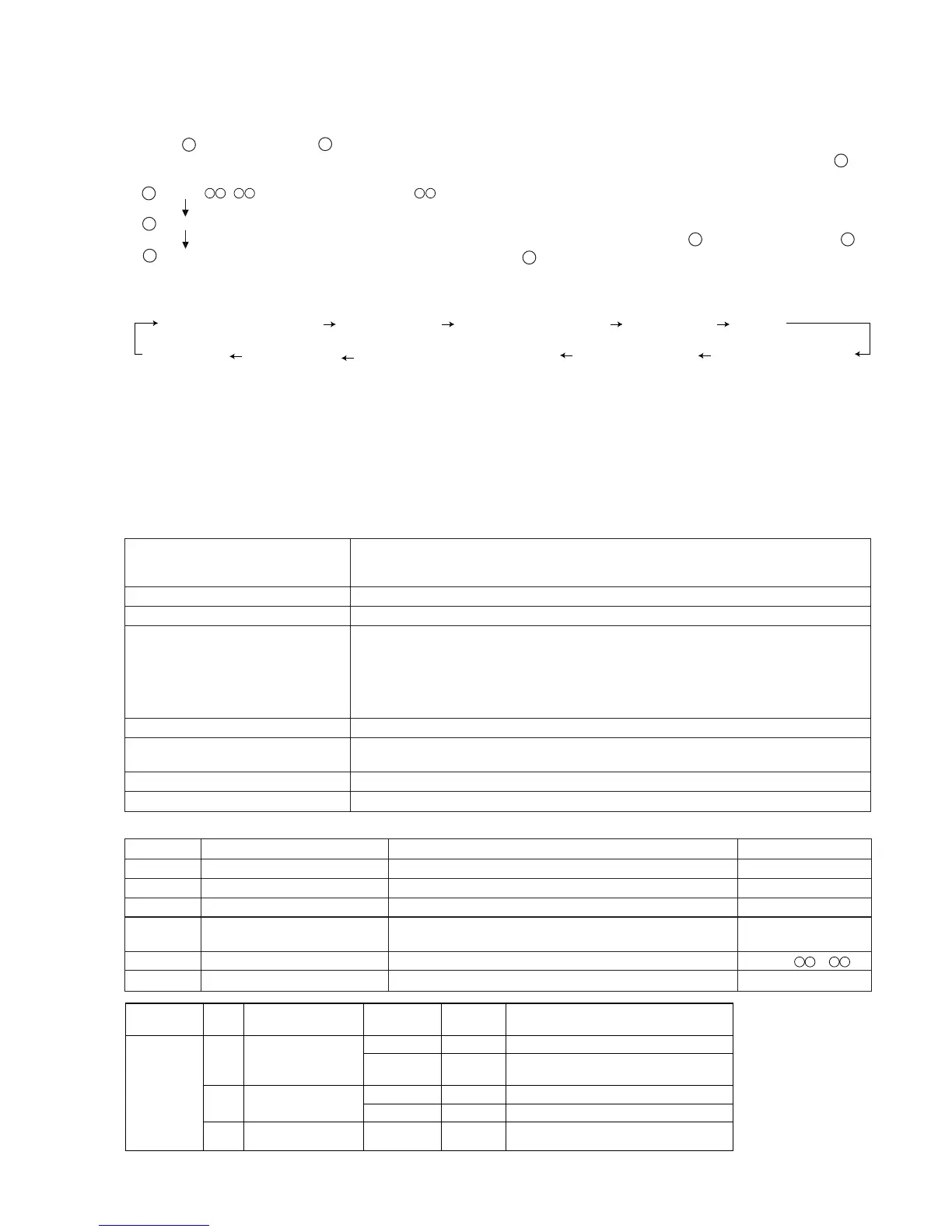
Test mode setting method
1. "MD TEST 1" ENTER.
(State A is changed to state B .)
2. Insert the playback-only disc 1 (high reflection disc) or the recordable disc 2 (low reflection disc). (State is changed to C.)
A tsm 1C e : TEST MODE represents version of MD microcomputer.
STOP state
B EJECT
C AUT AJST
2. Test Mode
Entering the specific mode
Whenever the EQUALIZER button is pressed, the mode is changed.
Cancel of test mode
To restore the usual state once reset.
*Before pressing the MENU button, be sure to perform the AUTO preliminary adjustment and the AUTO adjustment. Make sure
that they return a "COMPLETE" result.
*When the data of EEPROM was changed or the preliminary adjustment was performed again, be sure to press the MENU button
to write data in the EEPROM.
(Data is written in the EEPROM by pressing the MENU button.)
*When changing the EEPROM settings, write them into the EEPROM and then enter the test mode again. Perform the AUTO
preliminary adjustment and the AUTO adjustment. Then, write those into the EEPROM.
• Test Mode
1. EJECT mode • TEMP setting (of EEPROM setting)
• CONTROL setting (of EEPROM setting)
• Setting of laser power (record/playback power)
2. AUTO pre-adjustment mode • Automatic pre-adjustment is performed.
3. AUTO adjustment mode • Automatic adjustment is performed. (After adjustment the grating adjustment mode is set.)
• RESULT sub-mode • Therefore do not set this mode since it is not necessary for the service.
• RESULT mode (final adjustment)
• MANUAL pre-adjustment mode
• MANUAL adjustment mode
• MANUAL AFB adjustment mode
• ERROR DATA
4. EEPROM setting mode • Various coefficients of digital servo are changed manually.
5. TEST-PLAY mode • Continuous playback from the specified address is performed.
• C1 error rate measurement, ADIP error rate measurement.
6. TEST-REC mode • Continuous recording from the specified address is performed.
7. INNER mode • The position where the INNER switch is turned on is measured.
(When the MD STOP button is pressed in the C state, the indication A is
restored. To restore C again, press the EQUALIZER button.)
1. EJECT mode
Step 1 Test mode EJECT state [ _ _ E J E C T _ _ _ ]
Step 2
Press the DISP/CHARACTER button.
Playback power output state [ p p w _ _ _ _ _ _ _ ]
Step 3
Press the DISP/CHARACTER button.
Rec power output state [ r p w _ _ _ _ _ _ _ ]
Step 4
Press the DISP/CHARACTER button.
Therefore do not set this mode since it is not necessary [ x p w _ _ _ _ _ _ _ ]
for the service.
Step 5 Press the X-BASS button. TEMP setting of EEPROM setting [TEMP _ _ ]
Step 6 Press the PLAY button. CONTROL setting of EEPROM setting
Step No.
Setting Method
Remarks Display
MD TEST
Playback power output
[ppw]
DC0.2V
DC1.5V
To check 2
NG
–
Microcomputer may have recognized the PWB
as for playback-only. Perform check 1.
Recording power output
[rpw]
Cannot enter
[rpw] mode
DC1.8V
Below DC1.5V
Check end
NG
–NG
–
Perform check 2.
Microcomputer may have recognized the PWB
as for playback-only. Perform check 1.
Step Mode
Check items
Pin 3 of IC1401
Result Probable cause and remedy
1
2
AUTO YOBI
AUTO AJST
RST YOBI
AUT AFB
EEPROM_SET
MAN AFB
MNU YOBI
MNU AJST
ERR DATA
(ERRER DATA)
(AUTO prelimirary adjustment)
(AUTO adjustment)
(Advanced FAB adjustment)
(RESULT
YOBI)
RESULT
(MANUAL pre-adjustment)
(MANUAL adjustment)
(MANUAL advanced FAB adjustment)
(EEPROM setting)