EasyManua.ls Logo

Sharp CD-SW200 Service Manual

Sharp CD-SW200
124 pages
To Next Page IconTo Next Page
Page #1 background imageLoading...
Page #1 background image
CD-SW200
SERVICE MANUAL
In the interests of user-safety the set should be restored to its
original condition and only parts identical to those specified be
used.
No. S2510CDSW200/
SHARP CORPORATION
CONTENTS
Parts marked with " " are important for maintaining the safety of the set. Be sure to replace these parts with specified ones for
maintaining the safety and performance of the set.
This document has been published to be used
for after sales service only.
The contents are subject to change without notice.
CHAPTER 1. GENERAL DESCRIPTION
[1] Specifications ................................................. 1-1
[2] Names of parts............................................... 1-2
CHAPTER 2. ADJUSTMENTS
[1] Mechanism section ........................................ 2-1
[2] Tuner section ................................................. 2-1
[3] TEST MODE .................................................. 2-2
[4] CD SECTION ................................................. 2-4
[5] CD section...................................................... 2-4
[6] Standard Specification of Stereo System
Error Message Display Contents ................... 2-4
[7] CD Changer mechanism section ................... 2-5
CHAPTER 3. MECHANISM BLOCKS
[1] Caution on diassembly................................... 3-1
[2] Removing and reinstalling the main parts ........ 3-4
CHAPTER 4. DIAGRAMS
[1] Block diagrams............................................... 4-1
CHAPTER 5. CIRCUIT DESCRIPTION
[1] Notes on schematic diagram .........................5-1
[2] Types of transistor and LED ..........................5-1
[3] Waveforms of CD circuit ................................5-2
[4] Voltage...........................................................5-3
CHAPTER 6. CIRCUIT SCHEMATICS AND PARTS
LAYOUT
[1] Schematic diagram........................................6-1
[2] Wiring side of PWB...................................... 6-11
CHAPTER 7. FLOWCHART
[1] Troubleshooting.............................................7-1
CHAPTER 8. OTHERS
[1] Function table of IC .......................................8-1
[2] FL Display......................................................8-9
Parts Guide
CD-SW200
MODEL
CD-SW200 Mini Component System consisting of CD-SW200
(main unit) CP-S200 (front speaker) and CP-SW200 (sub-
woofer).
MINI COMPONENT SYSTEM

Other manuals for Sharp CD-SW200

Questions and Answers:

Sharp CD-SW200 Specifications

General IconGeneral
ModelCD-SW200
CD PlayerYes
TunerAM/FM
BluetoothNo
USB PlaybackNo
TypeStereo System
Amplifier Output Power20W + 20W
SpeakersIncluded

Summary

Important Service Notes

Safety Precautions Before Returning Product

Essential safety checks to perform before returning the audio product to the user.

Lead-Free Solder Information

Guidelines and procedures for using lead-free solder and related service.

Soldering Techniques for Lead-Free Solder

Best practices and considerations for soldering with lead-free solder.

General Description and Specifications

Product Specifications Overview

Detailed technical specifications for the CD-SW200 unit and its components.

Component Identification

Front Panel Components

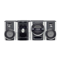
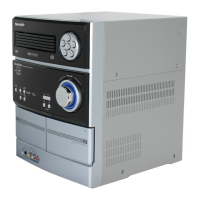
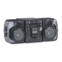
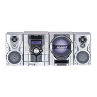
Identifies and lists all parts and controls on the front panel of the CD-SW200.

Display Panel Indicators

Lists and describes the various indicators on the unit's display panel.

Rear Panel Connections

Identifies and lists all connectors and terminals on the rear panel of the CD-SW200.

Remote Control and Speaker Components

Remote Control Operation

Lists and describes the functions of each button on the remote control transmitter.

Speaker System Components

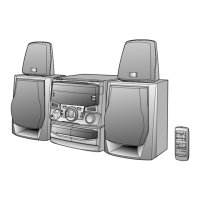
Identifies the parts of the CP-S200 front speakers and CP-SW200 subwoofer.

Adjustments and Calibration

Mechanism Section Adjustments

Procedures for checking and adjusting mechanism driving force, torque, and tape speed.

Tuner Section Calibration

Steps for calibrating AM IF/RF and FM RF/IF stages using signal generators.

Test Mode Procedures

Entering Test Mode

Instructions on how to enter the special test mode for diagnostics and adjustments.

Test Mode Operation Flowchart

Graphical representation of the sequence of operations within the test mode.

CD Section Operations and Error Handling

Automatic CD Section Adjustments

Details on automatic adjustment functions for the CD system, ensuring optimal playback.

CD Error Codes and Messages

Lists and explains CD error codes, including 'CHECKING' and 'ER-CD**' messages.

Preparing Unit for Transport

Step-by-step instructions for preparing the unit for safe transportation after servicing.

CD Changer Mechanism Details

CD Changer Mechanism Part Diagrams

Visual guide illustrating the assembly and arrangement of CD changer mechanism parts.

Cabinet Components and Assembly

Cabinet Parts Diagrams

Exploded views and diagrams showing the various cabinet parts and their assembly.

Front Speaker Assembly

Front Speaker Components Diagram

Illustrates the components and connections within the front speaker enclosure.

Subwoofer Assembly

Subwoofer Components Diagram

Illustrates the components and assembly of the subwoofer enclosure and its parts.

Packaging and Shipping Information

Packing Components for CD-SW200 Unit

Details on the packing materials and methods for the main CD-SW200 unit.

Packing Components for Speakers

Details on the packing materials for CP-S200 front speakers and CP-SW200 subwoofer.

Accessories and Service Parts

Included Accessories

Lists items included with the product, such as antennas and remotes.

Printed Wiring Board Assemblies

Lists the main Printed Wiring Board (PWB) assemblies, noted as not for individual replacement.

Other Service Parts

Lists miscellaneous service parts, including a lens cleaner disc.

Circuit Description Fundamentals

Notes on Schematic Diagram Interpretation

Explains symbols and conventions used in schematic diagrams for resistors and capacitors.

Transistor and LED Type Identification

Lists and identifies the types of transistors and LEDs used in the unit.

Circuit Performance and Voltage Data

CD Circuit Waveform Analysis

Displays and explains waveforms from various points in the CD circuit for analysis.

Component Voltage Measurements

Provides a table of voltage readings for various ICs and components for diagnostic purposes.

Circuit Schematics

CD Servo PWB Schematic Diagram

Detailed schematic diagram for the CD Servo PWB, showing component interconnections.

PWB Wiring Diagrams

Main PWB Wiring Diagram

Shows the wiring layout on the main PWB for component identification and tracing.

Troubleshooting Guide

CD Playback Issues

Troubleshooting steps for when the CD player does not function or play discs correctly.

CD Error Code "E-CD01" Diagnosis

Diagnostic procedures for resolving the "E-CD01" error message.

CD Playback Failure Analysis

Steps to diagnose issues when CD operation is accepted but playback fails.

Integrated Circuit Function Tables

CD Servo IC (LC78690E) Pin Functions

Detailed pinout and function description for the LC78690E CD Servo IC.

IC Block Diagrams and Functions

CD Servo IC (LC78690E) Block Diagram

Block diagram illustrating the internal structure and functional blocks of the LC78690E CD Servo IC.

Focus/Tracking/Spin/Sled Driver IC (LA6261) Function Table

Lists the pin functions for the LA6261 driver IC, crucial for servo control.

Parts Guide Overview

Integrated Circuits (ICs)

List of integrated circuits used in the unit, with part codes and descriptions.

Transistor Identification

List of transistors used, including part codes and types.

Diode and Filter Components

Lists diodes and filter components with their respective part codes.

Transformer and Coil Components

Lists transformers and coils used in the unit with their part codes.

Capacitors and Resistors

Comprehensive list of capacitors and resistors with part codes and values.

Other Circuitry Parts

Lists miscellaneous electronic components like connectors, switches, and cables.

Mechanical and Cabinet Parts

Lists parts for CD mechanism, changer mechanism, cabinet, and speakers.

Packing and Accessory Items

Lists packing materials, accessories, and PWB assemblies.

Other Service Parts

Lists specialized service parts not categorized elsewhere.

CD Mechanism Components

CD Mechanism Exploded View

Exploded diagram showing the assembly of the CD mechanism parts.

CD Changer Mechanism Components

CD Changer Mechanism Exploded View

Exploded diagram illustrating the assembly of the CD changer mechanism parts.

Cabinet Part Identification

Cabinet Components Exploded View

Exploded view showing the assembly of the main cabinet and chassis components.

Front Speaker Component Details

Front Speaker Exploded View

Exploded view illustrating the assembly of the front speaker enclosure and its parts.

Subwoofer Component Details

Subwoofer Exploded View

Exploded view illustrating the assembly of the subwoofer enclosure and its parts.

Packing Part Identification

Packing Components for Main Unit

Details on the packing materials and methods for the main CD-SW200 unit.

Packing Components for Accessories

Details on the packing materials for CP-S200 front speakers and CP-SW200 subwoofer.

Replacement Parts Ordering and Codes

How to Order Replacement Parts

Instructions on how to provide necessary information when ordering replacement parts.

Capacitor and Resistor Code Explanations

Explains the coding system used for identifying capacitor and resistor types and values.

Related product manuals