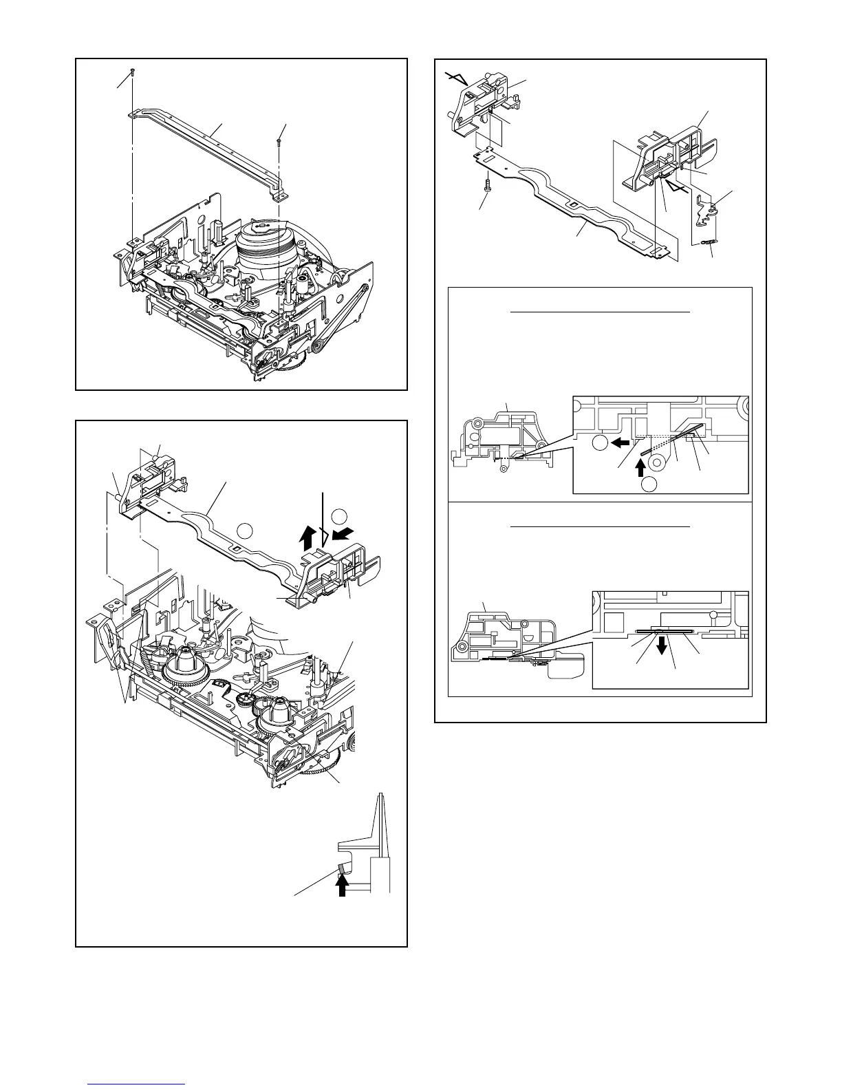
Fig. DM3
Fig. DM4
the slots A.
the slots B as shown.
[3]
[6]
[6]
(L-2)
Pin A
Hole A
Pin B
Hole B
(L-1)
First, insert [6] diagonally in [3] as shown below. Then,
install [6] in [3] while pushing (L-1) in a direction of
arrow. After installing [6] in [3], confirm that pin A of [3]
enters hole A of [6] properly.
Installation of [3] and [6]
View for A
2
1
[4]
Install [6] in [4] while pulling (L-2) in a direction of
arrow. After installing [6] in [4], confirm that pin B of [4]
enters hole B of [6] properly.
Installation of [4] and [6]
View for B
[3]
[4]
[5]
[6]
(L-1)
(L-2)
(P-1)
(L-3)
(S-1A)
A
B
Fig. DM5