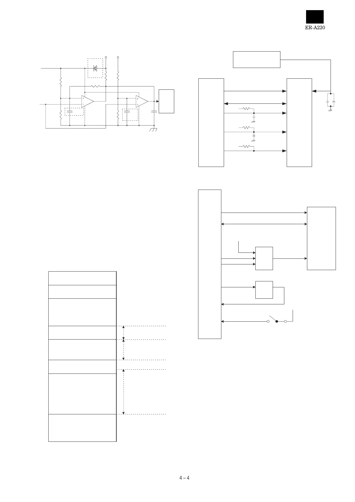
5. P-OFF circuit
The P-OFF signal detects two signals by two comparators and sent to
the CPU.
+24V signal : When the mode switch is placed in the OFF position,
the P-OFF output from the comparator: IC10A becomes
low to turn the power off.
When the mode switch is in positions other than OFF,
the P-OFF output from the comparator:IC10A becomes
high to turn the power on.
VCC signal : Though the MODE switch is at ON position, if the logic
power voltage Vcc falls below the specified level, the
P-OFF signal is driven to LOW by the comparator
IC10B.
6. Memory circuit
1) Address map
EP-ROM : Not available as standard equipment. The EP-ROM
socket is provided for rewriting the program for the CPU
internal FLASH-ROM.
2) RAM control
3) EP-ROM (IPL ROM) control
IC2 : EP-ROM (IPL ROM) is used to write data onto the CPU internal
FLASH-ROM.
+24V
VCC
+24V
VCC
R119
56K
R128
2.7K
3
2
1
8
4
IC10A
BA10393
5
6
7
8
4
IC10B
BA10393
R121
2.4KF
R122
13KF
D101
1SS353
P-OFF
C137
0.47uF
C138
0.47uF
C147
0.1uF
R120
3KF
R123
2.7KF
VREF
(2.495V)
P-OFF
19
Segment latch address
00000h
00400h
05400h
06000h
08000h
40000h
28000h
C0000h
FFFFFh
CPU internal RAM
20kbytes
External S-RAM : 128kbytes
(128kbytes area)
EP-ROM(For IPL) : 256k bytes
(512kbytes area)
CPU internal FLASH-ROM
256kbytes
/CS0 area
30000h - BFFFFh
*30000h - 3FFFFh :
Not used
/CS2 area
08000h - 27FFFh
/CS3 area
06000h - 07FFFh
CPU
S-RAM
128K byte
IC3B
A0-A16
D0-7
A0-A16
A0-A16
D0-7
I/O0-7
/CS2
/CS2
/CE
/RD
/RD
/WR
/WE
/WR
/OE
Power supply circuit
or
NI-MH battery
VDD
VCC
VDD
VCC
VCC
CPU
IC5B
P71
/HOLD
IC5B
VCC
/CS0
/OE
D0-D7
A0-A17
VCC
SHORT PIN
CNVss
SP1
IC2
EP-ROM
(IPL ROM)
D0-D7
A0-A17
/RD