CHAPTER 5. TEST FUNCTION
1. General
1) This diagnostic program has been developed for diagnosing ma-
chine functions in the field. The program is contained within the
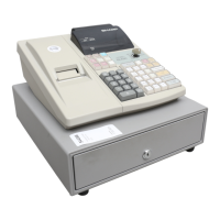
ER-A220.
The diagnostic program is stored in the CPU internal Flash mem-
ory which will be executed by the CPU (M30624FGFP) which re-
quires the following diagnostic operations :
a) Proper power supply voltages are mandatory for logic circuits
(+5V, VDD, POFF, +24V, 5.7V, 7.7V).
b) CPU input/output pins, CPU internal logic, system bus and
RAM must be working properly.
2. Operational procedure
To start the diagnostic program, you must enter the following com-
mand.
3-digit test item number
key in the SRV mode
The RAM must be operating properly to go into this mode. This is
necessary because the control jumps to the program area in the SRV
mode. A master reset must be performed before operating the ECR for
the first time. After any option is installed, a program reset is required.
When the master reset or program reset is performed, be sure to
check the printout on the journal paper.
Master reset : Turn power on in the SRV’ mode and change it to
the SRV mode with the PAPER FEED key
pressed.
print : MASTER RESET ***
Program reset : Turn power on in the SRV’ mode and change it to
the SRV mode.
print : PRG. RESET ***
3. Test command list
With the SRV mode and the following test code entry, the test start.
CODE DESCRIPTION
100 Display & Buzzer test
101 Key code test
102 Printer test
104 Keyboard test
105 Mode switch test
106 Printer sensor test
110 Drawer open test
120 External RAM test
121 CPU internal RAM test
130 CPU internal ROM test
140 CPU internal Flash ROM test
500 RS-232 loop back test
550 Sleep mode test
4. Test contents
[1] Display & Buzzer test
1) Key operation
2) Functional description
Display the following message on the front and the rear display
boards.
Front display
Pop-up display
A decimal point shifts from lower number of digit by one digit (per
200m sec.).
Next, display the following segments (for approx. 1 sec.).
Front display
Pop-up display
Repeat the above two kinds of displays.
Sound a buzzer continuously during test.
3) Check items
a) The display must be correctly shown at each position.
b) The luminosity of displays must be uniform and even at each posi-
tion.
c) Abnormal buzzer sound is not allowed.
4) Test termination
Press any key. The test terminates with the test and message printed
[2] Key code test
1) Key operation
100
#/TM/ST
1. 2. 3. 4. 5. 6. 7. 8. 9. 0.
4. 5. 6. 7. 8. 9. 0.
8. 8. 8. 8. 8. 8. 8. 8. 8. 8.
8. 8. 8. 8. 8. 8. 8.
1 0 0
101
#/TM/ST