ER-A520/A530 Dealer Knowledge Book
Page 250 of 266 Specifications subject to change without notice: Revision date 10/07
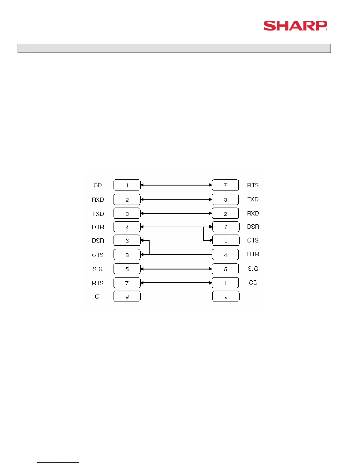
Cable Specifications
The RS232 function is used to download the logo image to the ER-A520/530 from the PC. Your SIO
function is dedicated to CHANNEL 2.
The below diagram represents the cable specifications required when connecting the ER-A520/530 to a PC
when the Logo Image Data function is used.
1. Specifications:
(1) Extension Cable: Shielded, twisted pair, 24 AWG
(2) Connectors: D Sub 9 pin (female type) connector
(3) Baud Rates: 38400
2. Pin Outs:
ECR ECR
9-pin D-Sub 9-pin D-Sub
Note: Pin #9 is not use
SD: Transmitted Data
RD: Received Data
DTR: Data Terminal Ready
DSR: Data Set Ready
RTS: Request to Send
DCD: Data Carrier Detector
CTS: Clear to Send
SG: Signal Ground