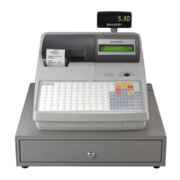
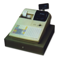
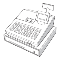
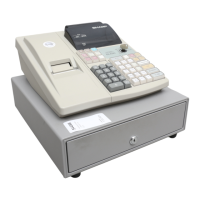
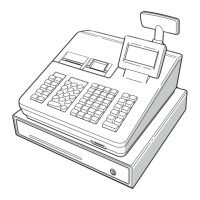
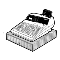
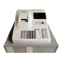
ER-A520/A530
– 1 –
CHAPTER 1. GENERAL
This manual describes the ER-A520/A530 disassembly procedures
and the option attachment procedures. For assembly procedures,
reverse the disassembly procedures. For attachment of options which
do not require special descriptions, descriptions are omitted.
Note for operations
• Before operation, ground the operator’s body and perform other nec-
essary measure against static electricity.
• During operations, disconnect the AC cord from the outlet.
• After completion of operations, connect the connectors.
• After completion of operations, be sure to perform the master reset.
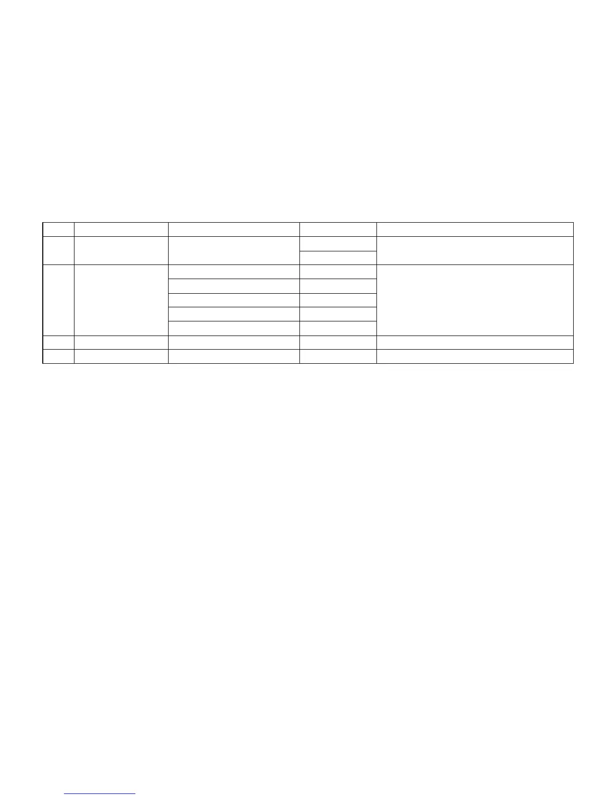
■ OPTIONS
NO CLASSIFICATION COMPONENT NAME MODEL NAME REMARK
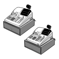
1 Drawer Remote drawer ER-03DW
ER-04DW
2 Key kit 1 x 1 key top kit (30) ER-11KT7 ER-A520 only
1 x 2 key top kit (30) ER-12KT7
2 x 2 key top kit (10) ER-22KT7
1 x 1 dummy key kit (30) ER-11DK7G
5 x 1 dummy key kit (10) ER-51DK7G
3 Display Customer Pole Display UP-P16DP
4 Memory RAM board UP-S02MB