ER-A520/A530
– 6 –
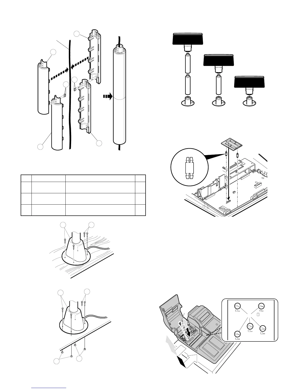
8) Install the attached pole cabinet G to the pole cabinet 7 to fix it
with the screw H.
9) Install the pole cabinet G in the opposite order of the disassembly.
10) Fastening on the table:
Secure the Base cabinet 2 using the screw.
Lowering the height of the UP-P16DP
Remove the standard Pole and attach the Base cabinet to the Ratch .
CHAPTER 6. E
XPANSION RAM BOARD
(UP-S02MB)
CHAPTER 7. DRAWER POSITION
CHANGE
1) Remove the cabinet fixing screw 1.
2) Slide the cabinet to the left, and remove the cabinet.
3) Insert the pawl of the cabinet into the hole A at the back.
4) Slide the cabinet to the right.
5) Tighten the cabinet fixing screw 1.
No. NAME USE Q’ty
I Screw (M4 x 16)
Securing the UP-P16DP to the
wooden table
4
J Screw (M4 x 20)
Securing the UP-P16DP to the metal
table
4
K Nut
Securing the UP-P16DP to the metal
table
4
Display cable
7
7
11
11
12
12
13 13
14
14
15
15
memory board
main board
A
1