ER-A520/A530
– 5 –
CHAPTER 5. POLE DISPLAY UNIT : UP-P16DP
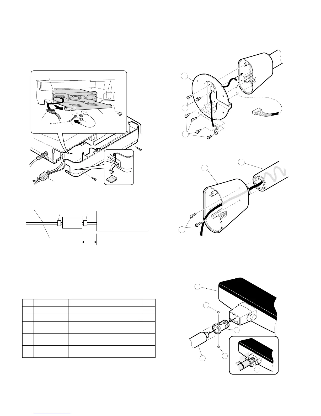
1) Remove the rear cover.
2) Connect the display cable 1 to the POLE connector 2.
3) Fix the earth wire 3 to the main chassis 4 with a screw 5.
4) Install the core 6 to the display cable 1 and earth wire 3.
Secure the core 6 with two wire bands.
Note: Install the ferrite core in a position less than 50mm from the cab-
inet.
n How to extend display pole:
UP-P16DP
The pole can be extended by installing the attached pole to the stan-
dard pole.
COMPONENT LIST:
1) Remove the five screws 1.
2) Remove the Base angle 2.
3) Remove the two screws 6.
4) Remove the Base cabinet 4 from the pole cabinet 7.
5) Turn the ratchet 9 connected to the pole cabinet 7 to the remov-
ing position and pull it out from the display unit 8 as shown in Fig.
A.
6) Remove the two screws F .
7) Remove the pole cabinet 7 from the Ratchet 9.
No. NAME USE Q’ty
G Pole cabinet Pole extension 2
H Screw (M2 x 8) Pole connection 4
I Screw (M4 x 16)
Securing the UP-P16DP to the
wooden table
4
J Screw (M4 x 20)
Securing the UP-P16DP to the metal
table
4
K Nut
Securing the UP-P16DP to the metal
table
4
1
2
3
5
6
4
Earth wire
Cabinet
MCR cable
Wire bandWire band
Core
Within 50mm
1
1
2
7
4
6
8
10
7
10
9
9
Fig. A